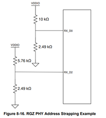
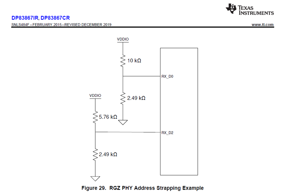
When using the RGX package, can you explain how figure 29 gives a PHY address of 0b1001? In that figure, shouldn't RX_D3 be tied asserted high instead of RX_D2, and RX_D1 and RX_D2 grounded? I'm trying to figure out how the PHY_ADD0-PHY_ADD3 correspond to the strapping in Table 5. During 'strapping time', doesn't PHY_ADD0-3 correspond to the strapping of RX_D0-3?

-
Ask a related question
What is a related question?A related question is a question created from another question. When the related question is created, it will be automatically linked to the original question.