This thread has been locked.

If you have a related question, please click the "Ask a related question" button in the top right corner. The newly created question will be automatically linked to this question.

SN65HVD3085E: Connection of batteries with low side switch

Part Number: SN65HVD3085E
Other Parts Discussed in Thread: ISO3086T, ISO1412, SN6501, ISOW1412

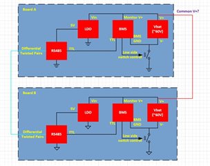
Is there any isolation neccesary if the common ground between devices might be turned off and the devices are connected by the high side (60V) and connection pins only?

The high side might differ in potential. Different charge status (35V - 59V) and in worst case even in nominal voltage (36V and 50V that results in 10S with 25 V min. and 14S with 59V max.)

If the difference is above a few Volts the low side of  the batteries with lower voltage will not be connected to the common ground. The levels have to be communicated before through a bus.

  • Christian,

    An engineer has been assigned to this thread and will respond by end of business 03/05/2024.

    Regards,

    Eric Hackett 

  • Christian,

    Do you have a block diagram of your system and where these high voltages would sit? (It seems like you're suggesting our device would be separated by a switch from it's GND pin to actual GND) For the SN65HVD3085E device you have tagged, those voltages would violate the absolute max ratings for it. Without common GND, I'm not entirely sure what would happen to the devices seeing the large voltages.... GND is used to bias silicon substrates for CMOS structures so without a common GND this might cause current to flow somewhere it shouldn't. 

    -Bobby

  • Dear Bobby.

    Thanks for your answer. The schematics is simple:

    BATTERY1 with voltage regulator 5V and RS485 device

    <-- connection: RS485-A & RS485-B & Battery+ ->

    BATTERY2 with voltage regulatror 5V and RS485 device

    And yes, the lack of a common GND instead of common Batt+ gives me headaches too. But the BMS switches low side and I have to manage data communication around that situation.

    Galvanic isolated ISO3086T would add complexity, price and power consumption in standby mode.

    Thanks in advance for more information and a solution.

    -Christian

  • Christian,

    Is this block diagram correct? I'm having a hard time following since there is a question of what GNDs are common to each other.

    In the example above, if the BMS cuts off the common GND between the RS485 device and the BMS and the RS485 device could see voltages that shift away from each other and damage could occur to the device through its TTL logic. 

    If the LDO is also not sharing the same GND as the RS485 device, the shift could occur at the Vcc pin and the RS485 could get damaged.

    Relative to the RS485 GND, any pins that are connected to the RS485 device that don't share the same GND and could outside of it's absolute maximum ratings and damage the device. 

    The only solution I can think of is to try to put clamping diodes on any pins which could drift to ensure the device doesn't break. The alternative is maybe use an isolated RS485 transceiver. 

    -Bobby

  • Dear Booby.

    Your block diagram wouldn't work as the electronics would not operate. The switch only disconnects the GND line to the outside world (between batteries and load etc.)

    The MCU / RS485 / internal power supply is constantly connected to V- of the battery pack.

    I will use an isolated transceiver as you have a great selection of those - just to make sure it works without giving options to break.

    -Christian

  • Hi Christian,

    Your block diagram wouldn't work as the electronics would not operate. The switch only disconnects the GND line to the outside world (between batteries and load etc.)

    The MCU / RS485 / internal power supply is constantly connected to V- of the battery pack.

    This makes much more sense. When I was constructing this, the design didn't make sense as to why the GND between all of the devices on the PCB and the remote battery would disassociate and be left in an unknown GND potential state. Cutting off GND from an external connection would make more sense here though I would normally expect the power rail to be disconnected from external sources. In daughter card connection boards, GND is always connected first and Power connected last to ensure GND states are common before power turns on, and when disconnected the Power is removed first then GND last. I figured other applications would follow this principal by keeping common GNDs and disconnecting power when a disconnect is required.

    I will use an isolated transceiver as you have a great selection of those - just to make sure it works without giving options to break.

    Do you need help selecting an isolation device? I can reassign this thread to the product line responsible for those parts to help you.

    -Bobby

  • Hi Bobby.
    Would be appreciated. I made my choice but it's quite pricey and I consider a cheaper solution in combination with FlyBack power. Hence please connect me with a person who can help me with a selection of RS485 and power supply for the entire electronics.
    - Christian

  • Hi Christian,

    I will reassign this thread to the isolation team for help with an Isolation RS485 device. After they help with that selection they will likely reassign this thread to someone in the power supply production for a product recommendation. 

    I suspect they should get back to you by the beginning of next week.

    -Bobby

  • Hi Bobby, thanks for transferring this to Isolation Devices Team. 

    Hello Christian, 

    ISO1412 is a common choice for isolated RS485 and is paired with SN6501 for isolated power (an isolated transformer driver). You can find our Isolated RS-485 transceivers product selection guide here. 

    In the product selection guide, you should see an option for ISOW1412 which provides integrated power. 

    I hope this helps, and feel free to follow up with a new thread if you'd like more details.

    Best,
    Andrew 

  • Hi Andrew.

    Thanks for following up the topic. What is the advantage of the split configuration of RS485 and seperate isolated power. I skipped this so far as I didn't find a good recommodation for a small size and well priced transformer that's suitable.
    Furthermore I liked the Enable Pin EN/FLT of the W version to be able to get lower power states something not available with SN6501 or a fly back solution on top of the main converter. But I would be grateful to learn more about that.

    Have you read the previous posts and agree that the situation needs an isolated RS485 or can this be circumvented? The ISOW is not very convenient for a final product in our price range.

    regards,
    Christian

  • Hello Christian, 

    We have transformer recommendations in the datasheet of SN6501. The advantages for using a discrete isolated power solution are you have better thermal performance with the transformer separated. You also will have a wider range of voltage output options since you have control over the transformer that is used. SN6505 would also give you an enable pin to get the lower power state if needed. 

    Have you read the previous posts and agree that the situation needs an isolated RS485 or can this be circumvented? The ISOW is not very convenient for a final product in our price range.

    I have reviewed again in more detail. From my understanding, it looks like you have 2 boards, and you are expecting the ground potential to be very different (outside the RS485 standards allowed common-mode voltage range). It is recommended to have some form of isolation between RS485 nodes if this is true. Adding an isolator and isolated power on both boards would allow the RS485 bus to operate on its own GND reference without having to worry about GND potential shifts on the other sides of the isolators. 

    Let me know if you have further questions.

    Best,
    Andrew