This thread has been locked.

If you have a related question, please click the "Ask a related question" button in the top right corner. The newly created question will be automatically linked to this question.

LMH0397: Footprint details

Part Number: LMH0397

Hi,

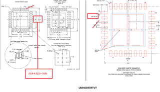
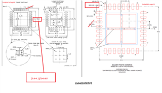
Am using the LMH0397RTVT part in my design, but in the datsheet i see two recommended footprints in page 44 and page 51 for same package, also there is diffrent in the pin length. PLease let me know why two footprint is used and which one to follow.

Regards

Balkis

  • Hi Balkis,

    Can you explain a little more? See this image from the datasheet:

    The solder paste will go over the pin layout, so it will be larger.

    Best Regards,

    Nick

  • HI NIck,

    Thanks for the response.

    My question is why the same part in datasheet has two different footprint recommendation? and both are with different pad size.

    Regards,

    Balkis

  • HI Nick, 

    Sorry for inconvenience, earlier attached image i have pointed the wrong pad value. Here is the corrected one.

    Please check red boxes in images, these are two different footprint provided in single datasheet. This is making confusion for our team to create footprint. Kindly confirm us this asap.

    Thanks and Regards,

    Balkis

  • Hi Balkis,

    Image on the left is the actual device pad size. On the other hand image on the right is used by your pcb assembly to deposit solder paste so device would have a reliable contact with the pcb. In summary, for your pcb layout please follow left hand side image. Then you can provide image on the right hand side to your assembly house where they are going to solder the part and place other components.

    Regards,Nasser