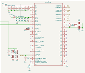
I am designing a board which has four ICs (FT4232H Quad High Speed USB to Multipurpose UART/MPSSE IC) capable of converting four serial RS-232 signals into one USB differential signal, all of which operate in USB2.0 standard protocol. I would like to incorporate the TUSB4041I Four-Port USB 2.0 Hub to combine these four USB signals into a single upstream USB A connector. The board would be self-powered with 5V. Given that there is no power draw from downstream ports I have a few questions about how to set up the Hub so that it is compliant with this design:Since the only connections downstream are for D+/D- I assume that there is no condition in which a given port would experience overcurrent. Given this I do not implement power switching and leave all PWR pins unconnected.
- Traditionally I program an EEPROM on each of the downstream ports through the UART to USB ICs using a direct USB mini connector. I must do this to set the VID and PID for each of these ICs so that they are recognizable as different entities. Would I be able to write to these EEPROMs separately through this Hub IC, or should I implement USB mini connectors along the downstream USB signals to directly interface with each of these serial converters and their EEPROMs. Additionally if the latter is the case, will this introduce noise which would undermine the signal on the downstream ports?
- Other TI USB hubs such as the TUSB2046 IC discuss the implementation of transient suppressors and noise reduction circuitry on the USB differential signal pairs; however there is no such mention for this IC. Are there internal components for ESD protection and signal integrity? And if not what guidelines should I follow to implement this externally?
- I am concerned about the conditions for the RESET signal. I use the same 3.3V and 1.1V regulator as the Evaluation board for this HUB IC, where the 1.1V regulator has a 200 us delay. Based off of the timing table and diagram from section 7.6 of the datasheet its states I need an active reset; however, the Evaluation board connects GRSTZ to ground with a 0.1uF capacitor as if the Hub was set for a passive reset which assumes the VDD must be stable before VDD 3.3 which is the opposite of what was just assumed. Is this correct to implement?