Other Parts Discussed in Thread: THVD8000,
Hi team:
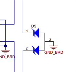
can you help to share the spec / the part number of D5 in EVM?
We found that this diode will pull the carrier wave low when there is no data communication, tks for checking.

This thread has been locked.
If you have a related question, please click the "Ask a related question" button in the top right corner. The newly created question will be automatically linked to this question.
Hi team:
can you help to share the spec / the part number of D5 in EVM?
We found that this diode will pull the carrier wave low when there is no data communication, tks for checking.

Hi Allen,
D5 is CDSOT23-T12C - its a bi-directional diode and won't, under normal circumstances, pull the line down.
That being said - the THVD8000 A and B pins will weakly pull the bus to 0V if there is no active communication.
Why is this a problem in the system?
A bus voltage of 0V should default to being read as a "High" on the "R" pin of the device in RX mode - essentially when the bus is idle the output should be high.
Best,
Parker Dodson
Hi Parker,
tks for the comments here.
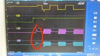
We tested the voltage of each pin of the IC against GND, and found that after MODE changes from 0 to 3.3V, a common mode pulse will be generated in A and B, as shown in the red circle in the picture. can you share what is the reason for this?
CH1:D
CH2:MODE
CH3:A
CH4:B

Hi Allen,
Usually common mode shifts like that are the result of parasitic on the line that can have overshoot/undershoot possibly also some oscillation - the system is comprised of inductors and capacitors typically so it could be partially to do with the coupling network itself.
1) What do you have connected to the EVM during test?
2) Are you measuring at the output of A/B or beyond the coupling network capacitors (i.e. measuring the shared-bus A and B - such as measuring at the terminal block) ?
Please let me know!
Best,
Parker Dodson
Hi Parker,
During these test , customer just use THVD8000EVM only , and the test point is output of A/B of THVD8000 IC.
Hi Allen,
It is most likely due to the LC network on the EVM then. There is a lot of capacitance and inductance on the board (this is because it allows multiple modulation frequencies to be tested without changing components) - so there will be some overshoot/undershoot/oscillations in the common mode during a mode switch. You can kind of see it during the data-transmission but its too a lesser degree (smaller signal levels).
It is common mode though so it is rejected by the receiver - receiver only cares about differential voltage. To limit common mode noise using common mode chokes in real applications can be beneficial.
Please let me know if you have any other questions.
Best,
Parker Dodson.