


Part Number: TDP1204
Brief Overview of HDMI PHY:
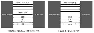
The HDMI physical layer is composed of 4 high-speed lanes, one Display Data Channel (DDC) which operates with I2C signaling, Hot Plug Detect (HPD) for device detection, Consumer Electronic Control (CEC), and HDMI Ethernet and Audio return Channel (HEAC). HEAC and CEC are both optional and do not affect video display.
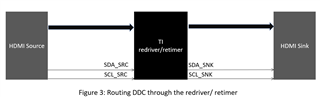
For HDMI 2.0 and earlier versions the four high-speed lanes are defined as Transition Minimized Differential Signaling (TMDS) channels [0-2] and TMDS clock. For HDMI 2.1 the signaling changes to Finite Rate Lane (FRL). In HDMI2.1 the four high-speed lanes are defined as FRL lane [0-3], where the TMDS clock lane becomes FRL lane 3 and TMDS lane [0-2] becomes FRL lane [0-2].
The following diagram highlight the similarities and differences between previous HDMI versions and HDMI 2.1
DDC Overview:
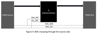
The DDC is used to control the status and configuration of the HDMI high-speed lanes. The signaling of the DDC is I2C, so the DDC is composed of the Serial Data (SDA) and Serial Clock (SCL) lanes. HDMI redrivers and retimers will have a SDA/SCL_SRC (source side connection), and a SDA/SCL_SNK (sink side connection). These are the pins that will be used for DDC snooping.
How to snoop HDMI:
There two are ways to route DDC when using a redriver/ retimer. Option 1 is routing through the redriver/ retimer and using the internal DDC buffer as seen in Figure 3.
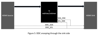
Option 2 is to route the DDC lanes around the redriver/ retimer. In this case depending on the device pin definitions you need to connect the SDA and SCL line to the source side or sink side in order to snoop the DDC. This can be seen in Figure 4 and Figure 5.
DDC snooping is used to correctly configure the redriver/ retimer to be in alignment with the source and sink. The snoop enable setting will be found in datasheet of the redriver/ retimer.
If the redriver/retimer is in pin strap mode, DDC snooping is necessary to set-up the device properly.
If the redriver/ retimer has an I2C mode, DDC snooping becomes optional as the configuration registers can be set manually using an I2C controller, or automatically using DDC snooping
