This thread has been locked.

If you have a related question, please click the "Ask a related question" button in the top right corner. The newly created question will be automatically linked to this question.

TCAN1145-Q1: Device state question

Part Number: TCAN1145-Q1

Hello team,

I have a couple of questions regarding the device state.

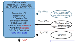
1) In case of switching to sleep mode with VSUP, VIO and VCC then the VIO and VCC are removed after a period of time, will it be stayed in Sleep mode? (If a trigger such as VIO<UVIO, we are concerned that there is a possibility to be the Fail-safe mode or the mask settings of WUF set during the Sleep mode transition will disappear.)
2) In case of shorting the RXD pin to GND then switching to Sleep mode with VSUP and VIO supplied, we confirmed that about 20mA current flowing from the RXD pin. In the Normal mode, we think that the current flowing from this RXD can be suppressed to the order of uA. Is it possible to suppress uA order in the same way by register setting etc. in the Sleep mode as well?

Thanks in advance.
S.Sawamoto

  • Sawamoto-san,

    An engineer has been assigned this thread and will respond by end of business 03/15/2024.

    Regards,

    Eric Hackett

  • Hi Eric,

    Understood, I'm looking forward to hearing from you soon.

    Let me add some additional information and correction as follows.

    Regarding 1), the customer has confirmed that the register value is maintained on the EVM in keeping Sleep mode after turning off VIO and VCC, so that is a kind of a confirmation if that is also correct from the design spec point of view.

    Regarding 2), there is a correction, ~ in the Standby mode, we think that the current flowing from this RXD can be suppressed to the order of uA. Is it possible to suppress uA order in the same way by register setting etc. in the Sleep mode as well?

    Thanks,
    S.Sawamoto

  • Hi team,

    I'm looking forward to hearing from you for a responce.
    If do you have any unclear thing, feel free to let me know.

    Thanks,
    S.Sawamoto

  • Hi Sawamoto-san,

    Sorry for the delay here. 

    1) In case of switching to sleep mode with VSUP, VIO and VCC then the VIO and VCC are removed after a period of time, will it be stayed in Sleep mode? (If a trigger such as VIO<UVIO, we are concerned that there is a possibility to be the Fail-safe mode or the mask settings of WUF set during the Sleep mode transition will disappear.)

    The Vio and Vcc undervoltage timers are disabled when the device is in sleep mode. It is expected that these supplies will be turned off when the transceiver is put into sleep mode as the typical application will have these supplies controlled by the INH signal. Because the INH signal is off in sleep mode, it is also expected that Vcc and Vio will be disabled in this state. 

    2) In case of shorting the RXD pin to GND then switching to Sleep mode with VSUP and VIO supplied, we confirmed that about 20mA current flowing from the RXD pin. In the Normal mode, we think that the current flowing from this RXD can be suppressed to the order of uA. Is it possible to suppress uA order in the same way by register setting etc. in the Sleep mode as well?

    While the transceiver is in sleep mode, the RXD pin will be in a high impedance state with an internal pull-up to Vio so long as this supply is available. When Vio is below UVio and when transceiver is in sleep mode, the RXD pin will be high impedance with a weak bias to ground. 
    When waking into standard mode from sleep mode, the RXD pin will be driven to ground potential to indicate the presence of a pending wake request. If standby was entered directly without a wake event, the RXD pin will be driven high (Vio level) by the transceiver. In both of these cases, the current through the pin is dependant on the leakage path that exists between the transceiver's driving pin and the MCU's input pin. This is typically in the uA range as the input resistance of the MCU pin is typically quite large. 

    What was the test setup that showed the 20mA current from the RXD pin? This current is far too high for a digital pin on this device and would exceed the absolute maximum rating and I would expect it to damage the device. Please confirm the magnitude of this reading. 

    Regards, 
    Eric Schott