Other Parts Discussed in Thread: TUSB501, TUSB211,

USB is not recognized.
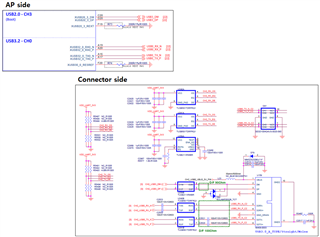
Please check the USB2.0 ~ USB3.0 RX/TX connection.
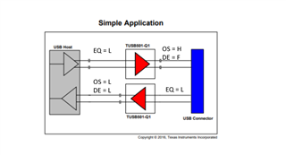
*. Option - OS: 4.7k Pd / EQ: 4.7k Pd / DE: NC
This thread has been locked.
If you have a related question, please click the "Ask a related question" button in the top right corner. The newly created question will be automatically linked to this question.

USB is not recognized.
Please check the USB2.0 ~ USB3.0 RX/TX connection.
*. Option - OS: 4.7k Pd / EQ: 4.7k Pd / DE: NC
Hi,
Can you please share the full connection between the AP to TUSB501 and TUSB211?
Are you seeing USB2 and USB3 not being recognized or just USB3?
Can you also share your layout?
Thanks
David
Only the net name is different, but it is a direct connection.
Layout sharing is difficult due to customer circumstances
Please check if there are any items other than the impedance item that may cause problems with the RX/TX connection.
Test content
- USB2.0/USB3.0 is recognized when TUSB501 parts are removed and connected directly with a wire.
Hi,
Looking at the TUSB501 portion of the schematic, you are missing the 0.1uF AC coupling cap on CH2_USB0_TX_P/N. USB3 would not work without the capacitor.
Thanks
David
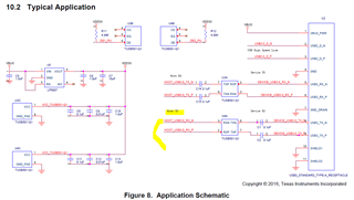
Looking at TUSB501-Q1 Datasheet (SLLSET3 – May 2016) 10.2 Typical Applications,
There is a note with HOST TX above in the HOST_USB3.0_RX_N net.
I created a circuit diagram referring to this circuit diagram.
Why is this different from David's instructions?
After passing through the redriver, a 0.1uF AC coupling cap is attached.

Hi,
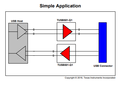
I believe Figure 8 was copied from the EVM we did which the HOST_USB3.0_RX_P/N and HOST_USB3.0_TX_P/N are connected to a USB plug. In this case, the AC coupling cap is provided on a USB host which the EVM will be plugged into. If the host and TUSB501-Q1 are on the same PCB, then you have to provided AC coupling cap for both TX and RX as shown in the simple application block diagram.

Thanks
David
Please check the reference value of the ac coupling cap.
ex) Based on Simple Application ( USB Host - TUSB501 - Con )
TX: 100nF - TUSB501 - 100nF
RX: 330nF - TUSB501 - X
Hi,
Please see below for the AC coupling caps value.
TX: 100 or 220 nF - TUSB501 - 100 or 220nF
RX: 100 or 220 nF - TUSB501 - X or 330nF
Thanks
David
Thanks David,
Is there a reference solution depending on the cable length used?
ex)
1. 3m
- EQ: High
- OS: Low
- DE: low
2. 6m
- EQ: Float
- OS: Low
- DE: low
Hi,
For each TUSB501-Q1, how long is the trace between USB host and TUSB501-Q1, and between TUSB501-Q1 and the connector?
Thanks
David
Connect from the TUSB501-Q1 on the test board to your desktop PC.
The distance is 6~7m.
Hi
I assume 6-7m is the cable length? What is the trace distance between AP and TUSB501-Q1 and TUSB501-Q1 to the USB connector?
Thanks
David
Thank you for answer
[ Cable Length ]
1. Test board(AP+TUSB501+Connector) -> Desktop PC
: 6~7m
[ PCB Patten distance ]
1. distance between AP and TUSB501-Q1
1) RX_N: 64.2503mm
2) RX_P: 64.2709mm
3) TX_N: 56.8246mm
4) TX_P: 56.8246mm
2. distance between TUSB501-Q1 to the USB connector
1) RX_N: 33.0658mm
2) RX_P: 33.0523mm
3) TX_N: 24.2877mm
4) TX_P: 24.3267mm
Hi,
Based on the trace length, below is my initial EQ, OS, and DE recommendation.

Thanks
David
Hi,
A typical passive USB cable assembly for 5G has a 7.5dB loss and is supported up to 3m of cable length (dependent upon the gauge of the wires in the cable). For this 7m cable, is this a passive or an active cable? The setting I provided is to compensate for the loss of fabrication board only, and leave the remaining loss compensation including the 7m cable for the desktop PC and the AP. You may increase the TUSB501-Q1 DE and EQ between the TUSB501-Q1 and the USB connector to provide more compensation, but the result is not guaranteed if this 7m cable loss is more than the spec'ed 7.5dB.
Thanks
David
This is a USB3.0 passive cable without circuitry.
I understand that that setting compensates for the PCB pattern length.
#. Is it possible with a combination of USB passive cable 7m=3m+Redriver+3m?
If there is a configuration that can be applied as above, please provide guidance.
Hi,
You can use TUSB501-Q1 EQ and DE to provide as much loss compensation as possible, and let the desktop PC and AP to provide the remaining compensation. But with this 7m passive cable insertion loss possibly out of the USB3 spec, USB3 may not work if the cable loss is outside the compensation range.
Thanks
David
Is there any solution that can make 7m possible using passive cables?
ex) 7m = Board + 3m + TUSB501 EVK + 3m + PC
Hi,
With 3m cable on both sides of TUSB501EVK, you can set EQ and DE both to the setting of floating and see if it works.
Thanks
David