Other Parts Discussed in Thread: HD3SS3212, TUSB321
Hi,
We have a project where we use your TI products for USB-C connector (TUSB321AI, HD3SS3212).
We have a problem with the behaviour of the CC1 and CC2 pins of the TUSB321AI.
We want to use the IC only in DFP mode, so there is no 887k pull-up on the VBUS_DET pin. The CURRENT_MODE pin is unconnected.

There are two different measurement results:
Case 1
I tried different USB C converters (e.g. USB C - USB A conv.), flash drives…
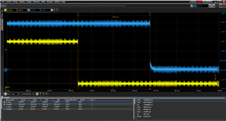
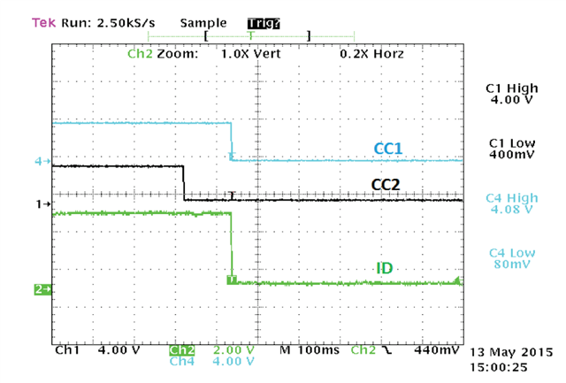
We measured 0V on one CC and 0.4V on the other. We do not understand why one CC goes down to 0V. We expect 5V here instead of 0V. The 0.4V is correct because we left the CURRENT_MODE pin unconnected. DIR output is always set correctly.

We tried to put the 887k PU on the VBUS_DET pin, then the previous 0V CC signals go up to 5V. What could be the reason?

I also made a scope plot of the behaviour of the CCs (cc1-cc2.png attachment).
Case 2
We plugged an Active cable into our USB-C connector and left the other end of the cable free.
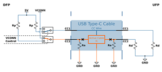
In this case one CC is always 80mV and the other is always 5V. We think that the measurement result is correct in this case considering the following diagram.

(Adding USB-C to your Carrier Board Design - Part 1 (toradex.com))
Best regards,
Benedek


