This thread has been locked.

If you have a related question, please click the "Ask a related question" button in the top right corner. The newly created question will be automatically linked to this question.

DP83TC813S-Q1: PMA Compliance Test Mode 1 expected output

Part Number: DP83TC813S-Q1

Hello

We are trying to enable the PMA compliance test mode 1 by checking on the BMSR register and confirm that the link is Up then write 0x2000 to register 0x1836 through the indirect accesses.

And we need to know what is the expected output waveform and on which pins ? to make sure that the configuration is reflected correctly into the registers and the mode is functional.

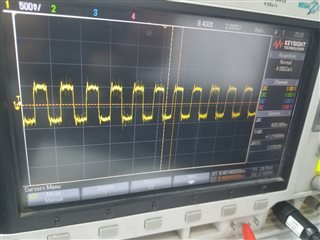
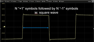
shall we monitor the differential output pins H and L and expect to have a square wave like the screenshoot below repeated continuously without any gaps in between?
As what we are currently obtaining when monitoring the differential output High pin is that the product always enters/exits test mode the time during which the product is in test mode is consistent to 800µs but the time between two test modes is variable (always few tens or hundreds of ms).

Screenshot attached for your reference, Ethernet is on channel 3 in blue and in the picture the product is in test mode for 800µs separated by 20ms around the two cursors X1 and X2.
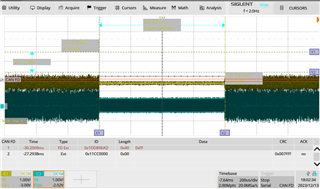
When I zoom in again:
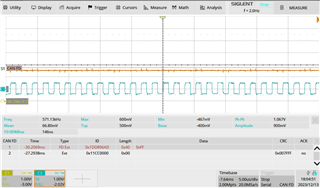
Appreciate your prompt response. 

  • Hi Heba,

    Test modes should not be used while link partner is connected. Please share a picture of your setup and how you are probing the signal. Expected test mode 1 waveform is a square wave as you have shown, yes. 

    Thanks,

    David

  • Hello David 

    Thank you for your replay 

    For your comment that "Test modes should not be used while link partner is connected ", in the snla389a document there is a note that from test mode1 preconditions that the link should be established between the DUT and the link-partner, could you please confirm is it required or not or advise if I'm not understanding the note correctly.

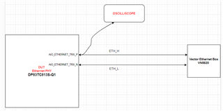
    Kindly find attached the diagram of our test setup. 

    Case 1:

    When disconnected the link-partner (i.e: ethernet box), obtained a continuous smooth square wave output signal without any gaps.

    Screenshot attached below 

    output signal when Link Partner NOT connected:

    Case 2:

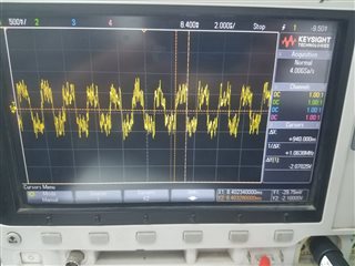
    When the link-partner is re-connected we obtain a square wave semi smooth (low noise) for some period, then the waveform interfered with high noise and its amplitude and shape impacted for some period then it return smooth again and this pattern is repeated continuously (Noise -> smooth ->noise ->smooth ,and so on) ,screenshoot attached below for the both waveforms with and without the noise.

    Output signal when link partner is connected and low noise:

    Output signal when link partner is connected and high noise:

    Could you please advise which case is correct and what might be the cause of the waveform corruption?

    Thanks

  • Hi Heba,

    This is a typo in SNLA389, thanks for pointing it out.

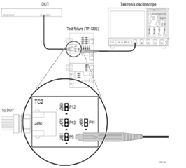
    Are you performing the transmitter output droop test? If so, the setup is as follows. Link should not be established. The device under test should be connected directly to the scope using a test fixture as follows. 

    Thanks,

    David

  • Hello David 

    Okay,Clear

    Thanks for your support!