This thread has been locked.

If you have a related question, please click the "Ask a related question" button in the top right corner. The newly created question will be automatically linked to this question.

TIC12400-Q1: Short to Ubat Switch - Resistor-Coded Detect

Part Number: TIC12400-Q1
Other Parts Discussed in Thread: TIC12400

Hi,

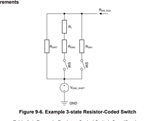
- I understand the resistor coded detection for switch to ground. The resistor and wettingg current multiply with each other and comparator is used at the IC.

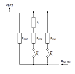
- But When I use the short to ubatt switch, How can I detect the different switch cases with resistor-coded switch logic?

Thanks,

  • Hi Samet,

    Using the resistor-code switch detection is designed to be monitored by the TIC12400’s integrated 10-bit ADC under configurable threshold. The SPI interface allows reporting of individual switch statuses. As you have mentioned, it sounds like you understand how to set the wetting current. Note that when using the resistor-coded switches, it is important to ensure the supply voltage is sufficiently high, or the device may not have enough headroom to generate accurate wetting currents (Section 8.4.3.3). Section 9.3 “Resistor-coded Switches Detection in Automotive Body Control Module” provides an example of how to configure switch detection (Table 9-5).

    I think to answer your question, when an input is setup in ADC input mode, the thresholds can be configured by setting the THRES_CFG1 to THRES_CFG2 registers (see Table 8-2). IN_STAT_ADC0 and IN_STAT_ADC1 can be read to determine if the inputs are above or below the set thresholds.

    Regards, Amy

  • Hi Amy,

    Actually, I didn't ask exactly this. For example, in the configuration Figure 9-6 in datasheet, by connecting different resistors to 3 different switches and adjusting the wetting current, I can understand which switch is active based on the voltage on the pin.

    So, in a configuration like the Figure 9-6, but connected to 12V instead of gnd, if I set the wetting current to, say, 5mA, and the battery voltage is also fixed at 12V, how can I detect which switch is active? Because it seems that the voltage on the pin will not change.

    Thanks,

  • Hi Samet,

    Thank you for clarifying, this was very helpful. I understand your question now. 

    The first example drawn in Figure 9-6 has the device configured to source the current. This configuration can only be implemented using input pins 0-9, as these are the only input pins that can source current. It sounds like you have a good understanding of this - simply apply Ohm's Law V=IR to calculate the required resistor based on your choice of wetting current. Note that the ADC range is from 0V to 6V. As an example, in this configuration and using the parameters you mention above (ie, wetting current of I = 5mA), the required resistance to reach the ADC (max) of 6V is 6V = 5mA * R, or R=1.2 kohm.

    In the configuration with external VBatt / setting the device to sink the current, you need to calculate the voltage drop across the resistor to get the voltage level on the input pin. The corresponding equation is then (VBatt-Vinx) = I*R. For example, using the parameters you mention above to reach the min/max voltage range of the ADC (0V -> 6V), working through the numbers you will find to get the ADC max of 6V, a 1.2 kohm resistor is required, and to get near the ADC minimum a 2.4 kohm resistor is needed.

    Also, take into consideration the resistance that could come from the switches as well as any resistor tolerances when making the final determination of resistor values to select.

    Hopefully this helps clear things up!

    Regards, Amy

  • This has been really enlightening, thank you. I hadn't come across a specific example regarding the resistor-coded section for transitioning to Ubat in the datasheet. I actually posed this question for the following reason: In the automotive industry, there's a need for us to diagnose open wire. There seems to be no distinction between the open state of digital switches and an open wire. We're considering configuring it as follows in software: By adding series and parallel resistors to the switch side to drop a certain voltage across it (as seen below), I believe 1.7V would be generated when there's an open wire. Do you think this approach is correct? Or if not, how can we achieve it ?

  • Hi Samet,

    I may have oversimplified the example above, but I am glad that this helped clarify. You are correct, in the case of sinking the current, you must take the additional voltage drop to ground as indicated in the datasheet clip you showed into account. To clarify how you can achieve what you have mentioned: 1) For an open wire: The floating INx pin will have a small offset voltage that the ADC will see; it will not be a true "0V". 2) For an open switch: The voltage level of the ADC will read greater than the open wire voltage that flows through the parallel resistor. 3) For a closed switch: The resistors in parallel will result in a lower overall resistance, and therefore a lower voltage drop, that will increase the INx pin voltage. Be sure to consider all these cases and plan out your component tolerances and voltage variations when choosing the ADC thresholds.

    Regards, Amy