This thread has been locked.

If you have a related question, please click the "Ask a related question" button in the top right corner. The newly created question will be automatically linked to this question.

SN65DSI86: SN65DSI86IPAPQ1

Part Number: SN65DSI86

Hi,

I am developing with STM32 L4 or U5 MCU.

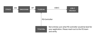
Could someone share how you got (LTDC, DSI, DMA2D, and SN65DSI86 Configuration) this bridge working with STM DSI?

Any help will be much appreciated.

Thanks

  • Hey Gustavo,

    With the information provided I can only help with the DSI86 configuration and some source driver code. Please keep in mind all software is provided as is and will not be supported or updated.

    DSI Driver code: https://github.com/torvalds/linux/blob/master/drivers/gpu/drm/bridge/ti-sn65dsi86.c

    DSI register calculator: https://e2e.ti.com/support/interface-group/interface/f/interface-forum/945404/faq-sn65dsi86-how-do-i-programming-the-sn65dsi86-registers?tisearch=e2e-sitesearch&keymatch=sn65dsi86#

  • Hi Vishesh

    Let me ask if this chip should be use for our purposes:

    Using a STM32 MCU (with no operating system running on it) generate a DSI signal which is fed into SN65DSI86-Q1 with the purpose to plug an over the shelf external monitor via USB-C. Is this feasible?

    I am asking because I simply cannot locate any literature about it.

    Thanks

  • One more question, if it is feasible, what would be the initial steps (software instructions) to have it working, knowing that any external display can be plugged into it.

    Thanks

  • You will need to do some DP alt mode configuration for DP over USB-C. Your system will need to look something like this.

  • Regarding the STM32, programming on this device is outside my area of expertise and I will not be able to support much.

  • Vishesh

    Ok different question, ignoring I have STM32, could you list step by step of how do I need to program the DSI86 chip to just be able to display the default color pattern.

    The display is connected via USB-C 3.1 Gen2 Fully functional cable.

  • You will need to use USB-C in alt mode, so I am not sure this will work.

    Here is the script for the DSI86 color bar

    5706.1DP_4DSI_HBR_800x600_Color_Bar.xml
    <aardvark>
        <configure i2c="1" spi="1" gpio="0" tpower="1" pullups="1"/>
        <i2c_bitrate khz="100"/>
        
      <i2c_write addr="0x2D" count="1" radix="16">5C 01</i2c_write> <sleep ms="10"/>
    
       <i2c_write addr="0x2D" count="1" radix="16">FF 07</i2c_write> <sleep ms="10"/>
    
    ======DUMP CFR======
       <i2c_write addr="0x2D" count="0" radix="16">16 </i2c_write> <sleep ms="10"/>
    
    ======Read======
        <i2c_read addr="0x2D" count="1" radix="16">00</i2c_read> <sleep ms="10"/>
    
    
       <i2c_write addr="0x2D" count="1" radix="16">16 01</i2c_write> <sleep ms="10"/>
    
       <i2c_write addr="0x2D" count="0" radix="16">16 </i2c_write> <sleep ms="10"/>
    
    ======Read======
        <i2c_read addr="0x2D" count="2" radix="16">00</i2c_read> <sleep ms="10"/>
    
      <i2c_write addr="0x2D" count="1" radix="16">FF 00</i2c_write> <sleep ms="10"/>
    
    
    ======Single 4 DSI lanes======
    
      <i2c_write addr="0x2D" count="1" radix="16">10 26 </i2c_write> <sleep ms="10"/>
    
    ======DSI CLK FREQ======
    
      <i2c_write addr="0x2D" count="0" radix="16">12 </i2c_write> <sleep ms="10"/>
       <i2c_read addr="0x2D" count="2" radix="16">00</i2c_read> <sleep ms="10"/>


    ======enhanced framing======
    
      <i2c_write addr="0x2D" count="1" radix="16">5A 04 </i2c_write> <sleep ms="10"/>
    
    
    ======ADDR 0x93 CFR======
    
       <i2c_write addr="0x2D" count="0" radix="16">93</i2c_write> <sleep ms="10"/>
    
    ======Read======
        <i2c_read addr="0x2D" count="6" radix="16">00</i2c_read> <sleep ms="10"/>
    
    ======Pre0dB 1 lanes no SSC======
       <i2c_write addr="0x2D" count="1" radix="16">93 10</i2c_write> <sleep ms="10"/>
    
    ======L0mV RBR======
       <i2c_write addr="0x2D" count="1" radix="16">94 80</i2c_write> <sleep ms="10"/>
    
    ======POST2 0dB ======
       <i2c_write addr="0x2D" count="1" radix="16">95 00</i2c_write> <sleep ms="10"/>
    
    ======PLL ENABLE======
       <i2c_write addr="0x2D" count="1" radix="16">0D 01</i2c_write> <sleep ms="10"/>
       <i2c_write addr="0x2D" count="0" radix="16">0A</i2c_write> <sleep ms="10"/>
       <i2c_read addr="0x2D" count="2" radix="16">00</i2c_read> <sleep ms="10"/>


    ======Semi-Auto TRAIN ======
       <i2c_write addr="0x2D" count="1" radix="16">96 0A</i2c_write> <sleep ms="20"/>
    
    
    ======ADDR 0x0A CFR======
    
       <i2c_write addr="0x2D" count="0" radix="16">96</i2c_write> <sleep ms="20"/>
    
    ======Read======
        <i2c_read addr="0x2D" count="1" radix="16">00</i2c_read> <sleep ms="10"/>
    
    =====CHA_ACTIVE_LINE_LENGTH=======
        <i2c_write addr="0x2D" count="2" radix="16">20 00 04</i2c_write> <sleep ms="10"/>
    
    =====CHA_VERTICAL_DISPLAY_SIZE=======
        <i2c_write addr="0x2D" count="2" radix="16">24 58 02</i2c_write> <sleep ms="10"/>
    
    =====CHA_SYNC_DELAY=======
        <i2c_write addr="0x2D" count="2" radix="16">28 00 00</i2c_write> <sleep ms="10"/>
    
    =====CHA_HSYNC_PULSE_WIDTH=======
        <i2c_write addr="0x2D" count="2" radix="16">2C 80 80</i2c_write> <sleep ms="10"/>
    
    =====CHA_VSYNC_PULSE_WIDTH=======
        <i2c_write addr="0x2D" count="2" radix="16">30 04 80</i2c_write> <sleep ms="10"/>
    
    =====CHA_HORIZONTAL_BACK_PORCH=======
        <i2c_write addr="0x2D" count="1" radix="16">34 28 </i2c_write> <sleep ms="10"/>
    
    =====CHA_VERTICAL_BACK_PORCH=======
        <i2c_write addr="0x2D" count="1" radix="16">36 09</i2c_write> <sleep ms="10"/>
    
    =====CHA_HORIZONTAL_FRONT_PORCH=======
        <i2c_write addr="0x2D" count="1" radix="16">38 28</i2c_write> <sleep ms="10"/>
    
    =====CHA_VERTICAL_FRONT_PORCH=======
        <i2c_write addr="0x2D" count="1" radix="16">3A 01</i2c_write> <sleep ms="10"/>
    
    =====DP_18BPP_EN =======
      <i2c_write addr="0x2D" count="1" radix="16">5B 01 </i2c_write> <sleep ms="100"/>
    
    =====COLOR BAR =======
        <i2c_write addr="0x2D" count="1" radix="16">3C 10</i2c_write> <sleep ms="100"/>
    
    ======enhanced framing and Vstream enable======
    
      <i2c_write addr="0x2D" count="1" radix="16">5A 0C </i2c_write> <sleep ms="100"/>
    
    ======DUMP CFR======
        <i2c_write addr="0x2D" count="0" radix="16">20</i2c_write> <sleep ms="10"/>
    
    ======Read======
        <i2c_read addr="0x2D" count="32" radix="16">00</i2c_read> <sleep ms="10"/>


    </aardvark>
    

  • Vishesh

    I think we are to the point where we might need help from TI to work-out this project.

    So, could you tell me what would be needed from us for you (TI) help us design this project's hardware, as well as supporting us with the basic software configuration needed to get us up and running.

    Please let me know.

    Gustavo

  • Hey Gustavo,

    I can only support TI parts in you design. I unfortunately do not have the bandwidth to design your system for you.

    Best,

    Vishesh Pithadiya