This thread has been locked.

If you have a related question, please click the "Ask a related question" button in the top right corner. The newly created question will be automatically linked to this question.

SN65DSI83: SN65DSI83 sync error with STM32

Part Number: SN65DSI83

Hello.

I'm developing an application for an STM32F769 which has a 2-lane DSI host and will be connected to a 1024x600 18bpp LVDS panel.

I managed to get the panel working and display the test pattern on it, but I'm unable to get any image from the MCU.

For developing this application I started with a DSI to HDMI adapter, the code was adapted for 1024x600 resolution, and it displays correctly at 42.3Hz with a DSI speed of 400Mbit/s per lane, non-burst mode with sync pulses. That way I know that DSI stream is working.

Tested the panel at various clock rates and it should be able to work at this refresh rate using a clock frequency of about 25MHz

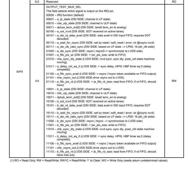
When debugging the SN65DSI83 what I find is that the LVDS stream is never started, and it generates a sync error interrupt (bit 7 of register 0xE5 is set all the time even if I clear it)

LVDS clock is generated from DSI clock, I made sure that DSI clock is continuous, there are no PLL errors.

The start sequence was also checked so when EN is asserted all lanes are in LP11, after 20ms registers are setup, then video stream is started and after that the PLL is enabled and a soft reset is sent to the SN65DSI83

What can be the cause of this sync error? It appears as soon as the stream is started, the IRQ line was configured and it goes high right after starting the stream. When starting the PLL it is also cleared and goes high again at the beginning of next frame.

I checked the settings with DSI Tuner and it should be ok, the minimum clock is 150MHz and the system is setup for 200MHz (400mbps)

Thanks for your help.

  • Hi Angel,

    As a start, can you share the .dsi file and panel specifications so we can verify the settings?

    Regards,
    I.K.
  • Hello I.K.

    I'm attaching the .dsi and panel datasheet. Renamed the .dsi to .txt as the forum didn't allow to upload directly.

    Thanks.

    F__规格书_COG-TA10MZXH-01_NEW SPEC_COG-TA10MZXH-01 specification.pdf

    sn65dsi83 stm32 1024.dsi.txt
    %CHIP1%PVCA%PMCA%RPCA1024%RLCA600%PVCB%PMCB%RPCB%RLCB%LVCM0%HPWA70%HBPA80%HFPA30%HACA1024%HTOA1204%HPWB%HBPB%HFPB%HACB%HTOB0%VPWA10%VBPA30%VFPA15%VACA600%VTOA655%VPWB%VBPB%VFPB%VACB%VTOB0%PCKN25%LCKS0%RCKM%MULT0%DCKA200%DIVI7%LCKR25.0%FMTA1%DEPA0%HSPA1%VSPA1%BPPA0%FMTB1%DEPB0%HSPB1%VSPB1%BPPB0%PRDA1024x600%PRDBx%DSCM0%LREO1%LRCE1%LPCA0%BMCA1%SMCA1%LPCB0%BMCB0%SMCB0%DHPA70%DHBA80%DHFA30%DHAA1024%DHTA1204%DHPB%DHBB%DHFB%DHAB%DHTB%DVPA10%DVBA30%DVFA15%DVAA600%DVTA655%DVPB%DVBB%DVFB%DVAB%DVTB%DDRA200%NOLA1%VIMA2%LCRP%DDRB%NOLB0%VIMB0%RCRP

  • Hi Angel,

    The tuner settings look okay. Can you check the line time provided by the DSI source? Is it the same 48.160us that the DSI Tuner is outputting? If the line time is different from what is calculated by the tool, this will cause issues since the DSI83 does not realign timing.

    Regards,
    I.K.
  • Hi again I.K.

    For making sure about the timings, I asked the manufacturer for their values as they were not present in the specification.

    Recalculated the configuration with the tuner and got 56.56us of line time.

    Adjusted the DSI clock to match this value, as the tuner showed that at 150MHz DSI clock the burst time will be exacly what I need. Checked with the oscilloscope that the host is sending data with the same line time.

    But sn65dsi83 still shows sync error all the time.

    What can be the causes for this error?

    I'm attaching the new .dsi and timing parameters of the panel.

    Regards.

    sn65dsi83 stm32 lvds.dsi.txt
    %CHIP1%PVCA%PMCA%RPCA1024%RLCA600%PVCB%PMCB%RPCB%RLCB%LVCM0%HPWA70%HBPA160%HFPA160%HACA1024%HTOA1414%HPWB%HBPB%HFPB%HACB%HTOB0%VPWA10%VBPA23%VFPA12%VACA600%VTOA645%VPWB%VBPB%VFPB%VACB%VTOB0%PCKN50%LCKS0%RCKM%MULT0%DCKA150%DIVI5%LCKR25.0%FMTA0%DEPA0%HSPA1%VSPA1%BPPA0%FMTB1%DEPB0%HSPB1%VSPB1%BPPB0%PRDA1024x600%PRDBx%DSCM0%LREO1%LRCE1%LPCA0%BMCA1%SMCA1%LPCB0%BMCB0%SMCB0%DHPA70%DHBA160%DHFA160%DHAA1024%DHTA1414%DHPB%DHBB%DHFB%DHAB%DHTB%DVPA10%DVBA23%DVFA12%DVAA600%DVTA645%DVPB%DVBB%DVFB%DVAB%DVTB%DDRA150%NOLA1%VIMA2%LCRP%DDRB%NOLB0%VIMB0%RCRP

  • Hi again.

    Doing some tests I have noticed that the IRQ line, configured for the sync error, goes high right after the vertical synchronization packet, its activation doesn't look to be related to line events but to the start of the frame.

    Don't know if this can be helpful or it is just normal behaviour of the chip.

    Regards.
  • Hi again.

    Did you have time to take a look at the new configuration I.K.?

    I'm attaching the interrupt event capture I mentioned in last post. Yellow trace is lane 0 positive signal, blue trace is IRQ line.

    It always asserts at that point, in the first line of the next frame after it was cleared, it looks to be set after receiving the sync pulse. There is a LP period of 2us between frames.

    Best regards.

  • Hi Angel,

    Sorry for the delay, I'm still looking into this issue. Can you attach the event capture? It looks like you forgot to attach it in your last post.

    Regards,
    I.K.
  • Hello.

    Yes, i forgot to attach it, here you have it. That one is configured for 25MHz LVDS, 200MHz DSI in two lanes, non-burst with pulses. Yellow trace is D0+ and blue is IRQ

    Since my first post I have done tests with different clocks, in burst, non-burst with event or pulses and enabling LP mode in different regions. I also tried another prototype unit to discard a damaged chip. And also tried reconfiguring another example for an actual display, instead the one for the HDMI converter.

    In all cases I receive this SYNCH interrupt at the start of the frame.

    I'm thinking about renting a high end oscilloscope with D-PHY decoding to dig into this deeper as mine is only 100MHz bandwidth.

    Best regards.

  • Hi Angel,

    I apologize for the delay in responding. When you say you tried another prototype unit to discard a damaged chip, does this mean you're seeing this issue on multiple SN65DSI83 units? When you configured the unit to generate a test pattern, did you use an external refclk to generate the LVDS clock, or were you still using the DSICLK?

    Regards,
    I.K.
  • Hi.

    That's it, I made a few boards and tested two of them, both boards with different SN65DSI83 units show the same behaviour. It is actually the SN65DSI83-Q1 but it is supposed to be the same chip just in QFP and with automotive qualification.

    The test pattern works both with DSICLK and with REFCLK, the idea is to use the DSICLK but modified one board with a 25MHz oscillator and tested the external clock as well to discard issues with the DSICLK. Most of the tests have been done with DSICLK as REFCLK didn't show any difference.

    With DSICLK the PLL unlock bit is never set so it must be working correctly, also the LVDS clock corresponds with the desired frequency of 25MHz when the test pattern is active.

    Best regards.

  • Hi Angel,

    To get a clearer indication of the failure, can you try configuring the internal test register, 0xF9? This field selects which internal signal is output on the IRQ output pin. You can configure this field during the power up. Once the sequence is completed you can know, by monitoring IRQ, if there are internal errors communicating from DSI to LVDS. You can start with trying a_wait_for_vsync. When it is configured the IRQ should remain low after the power-up sequence is completed and the device is operating correctly.

    The procedure for getting the status of a_wait_for_vsync from the test mux is the following:

    a. Enable IRQ output. Write 0x1 to address 0xE0 to set IRQ_EN=1.

    b. Set OUTPUT_TEST_MUX_SEL = 00110 (a_wait_for_vsync) by writing 0x06 to address 0xF9.

    c. Observe the test_mux output on the DSI85 IRQ pin.


    You can also check for other errors with the below table for IRQ functions.

    0xF9
    00000
    IRQ function
    Normal case
    ISSUE
    00001
    a_lp_state
    Toggling every x time
     
    00010
    cha_ulp_state
    High
     
    00011
    dphya_term_en[0]
    Toggling every x time
     
    00100
    a_sot_rcvd
    Toggling every x time
     
    00101
    a_dsi_rd_data_avail
    Toggling every x time
     
    00110
    a_wait_for_vsync
    Low
    00111
    a_dsi_clk_ratio_sync
    Toggling every x time
     
    01000
    a_dsi_sync
    Toggling every x time
     
    01001
    a_fifo_pix_wr
    Toggling periodically
     
    01010
    cha_sync_dly_state
    Toggling every x time
     
    01011
    a_delay_cnt_eq_0
    Toggling every x time
     
    01100
    a_fifo_sync_avail
    Toggling every x time
     
    01101
    cha_vsync_out
    Toggling every x time
     
    01110
    a_fifo_pix_rd
    Toggling every x time


    Regards,
    I.K.

     
    0xF9
    00000
    IRQ function
    Normal case
    ISSUE
    00001
    a_lp_state
    Toggling every x time
     
    00010
    cha_ulp_state
    High
     
    00011
    dphya_term_en[0]
    Toggling every x time
     
    00100
    a_sot_rcvd
    Toggling every x time
     
    00101
    a_dsi_rd_data_avail
    Toggling every x time
     
    00110
    a_wait_for_vsync
    Low
     
    00111
    a_dsi_clk_ratio_sync
    Toggling every x time
     
    01000
    a_dsi_sync
    Toggling every x time
     
    01001
    a_fifo_pix_wr
    Toggling periodically
     
    01010
    cha_sync_dly_state
    Toggling every x time
     
    01011
    a_delay_cnt_eq_0
    Toggling every x time
     
    01100
    a_fifo_sync_avail
    Toggling every x time
     
    01101
    cha_vsync_out
    Toggling every x time
     
    01110
    a_fifo_pix_rd
    Toggling every x time


  • Hi I.K.

    I have tested the device as suggested, with test mux set for a_wait_for_vsync the IRQ signal goes low immediately after the VSS event but goes high again after a few microseconds. After checking the times and playing with the configuration parameters it was clear that the low time corresponds to the sync delay time. Initially it was around 1,4 microseconds, for a PCLK of 25MHz this equals to 35 pixel time, setting was at 33 as suggested by dsi tuner.

    Increasing the delay time just increases the low time, until it gets to the next HSS. Decreasing it shortens the low time. A value of 1 makes the line go high all the time and a value 0 gives the same result as very long times, rising on next HSS event.

    Checked all the mux settings in previous post to try and get more info about the issue, this are the results:

    0xF9
    0 IRQ function Normal case ISSUE NOTES
    1 a_lp_state Toggling every x time OK HIGH DURING LP MODE
    10 cha_ulp_state High OK HIGH DURING LP MODE
    11 dphya_term_en[0] Toggling every x time OK HIGH DURING HS MODE
    100 a_sot_rcvd Toggling every x time OK SHORT PULSE EACH HS BURST, AFTER HEADER
    101 a_dsi_rd_data_avail Toggling every x time OK HIGH DURING HS MODE
    110 a_wait_for_vsync Low TOGGLING LOW ONLY DURING SYNC DELAY TIME
    111 a_dsi_clk_ratio_sync Toggling every x time OK HIGH DURING MOST OF HS HEADER
    1000 a_dsi_sync Toggling every x time OK VERY SHORT PULSE ON VSYNC
    1001 a_fifo_pix_wr Toggling periodically OK VERY SHORT PULSE ON VSYNC
    1010 cha_sync_dly_state Toggling every x time OK HIGH AFTER VSYNC FOR SYNC DELAY TIME
    1011 a_delay_cnt_eq_0 Toggling every x time LOW
    1100 a_fifo_sync_avail Toggling every x time OK HIGH AFTER VSYNC FOR SYNC DELAY TIME
    1101 cha_vsync_out Toggling every x time LOW
    1110 a_fifo_pix_rd Toggling every x time LOW

    From the mux settings description it looks like a_wait_for_sync should go high only after reset/soft_reset or error conditions. What kind of error can cause this behaviour? IRQ status register still shows only sync error bit.

    For making totally sure about the chips I'm ordering a couple of them from another provider, just to discard a bad batch.

    Thanks for all your help!

    Best regards.

  • Hi again.

    Finally managed to solve the problem, it was a really stupid mistake in the end. When initializing the registers, register 0x10 was being written directly, without checking its previous value. That resulted in some reserved bits being set to zero, so the DSI83 was  configured for dual link DSI which isn't supported by this version and is not the configuration needed for this application.

    Now we have a stable image in the LCD.

    Thanks again for all your support!

    Best regards.

  • Hi Angel,

    Great that you figured out the issue! I probably should have asked for a register dump in the first place, and we could have caught it much earlier.

    Regards,
    I.K.