Part Number: TFP410
Hi Sirs
We plan to use TFP410 to transfer RGB666 to HDMI signal.
So according to datasheet, I should use DATA pin 0~5 for Blue 0~5, DATA pin 8~13 for Green 0~5, DATA pin 16~21 for Red 0~5, right? Unused DATA pin to ground?
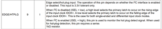
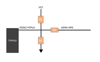
Another question is about Hot plug (pin EDGE/HTPLG), we paln to use a level shifter to transfer HDMI hot plug pin to 3.3V, then connects to pin EDGE/HTPLG, is that ok?
If this works, 1K series ohm still necessary?
Thank you