This thread has been locked.

If you have a related question, please click the "Ask a related question" button in the top right corner. The newly created question will be automatically linked to this question.

DP83869HM: MII loopback mode setup

Part Number: DP83869HM

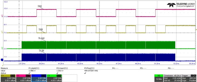
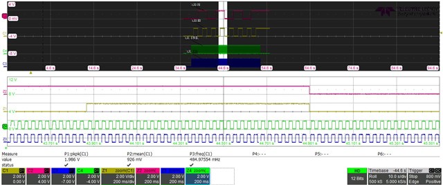
I am currently trying to do some functional testing of the PHY to verify the RGMII connection to an FPGA. I am using the JTAG Boundary scan cells to read and write signals. I am using Boundary scan instead of programming the FPGA itself, because we want to use JTAG in our production verification, without having to program the FPGA. This means That I am running at very low frequencies, the TX_CLK runs at arround 33Hz. So possibly here lie some of the issues, but the example projects we have gotten from JTAG for other PHYs use the same frequency and do not have any issues, so I have assumed these signals to be correct for this application, but have concluede some scope images anyway. Rx lines are not shown, but do not show any activity. 

Since I am unable to get anything on the RX lines at all, it leads me to believe that I have not configured the registers correctly to get it into MII loopback mode. Following the datasheet I have come to the following configuration:

Register    Name              Value

0xFE         LOOPCR        0xE720          (as specified by the datasheet, but not further specified what setting this register does)

0x0           BMCR             0x4100          (MII_LOOPBACK Enabled, Atonegotiation off, and still full duplex)

0x16         BIST                0x4                (tried with and without setting this register, datasheet implies that it would only be necessary when in 100Base-TX mode, but tried anyway)

I've read back these registers, so I am sure that they are set like I've mentioned them here. Is there something obvious that I am missing?
  • Hello,

    Please allow me to bring this topic to the team for discussion. Please expect a response around next week due to US holiday tomorrow.

    Sincerely,

    Gerome

  • Hi Gerome,

    Thank you for your response. Did you already have to time to look at this issue?

    Kind regards,

    Timber

  • Hi Timber,

    After talking with the team, we wanted to shift the debug away from JTAG related activities to trying to address the root cause of the issue you are seeing; RX signal not toggling. 

    First off, I want to ensure that the PHY is alive. Can you please read the following registers:

    0x0

    0x3

    0x6E

    0x1DF

    Sincerely,

    Gerome

  • Hi Gerome, 

    Thank you for looking into the issue.

    I've read the registers and the values are the following:

    Directly after reset:

    Register       Value

    0x0              0x1140

    0x3              0xa0f3

    0x6E            0x4

    0x1DF         0x40

    After Trying to do the loopback, like I described in initial message, only the 0x0 register changes to 0x4100 (because I set it like that), the other registers do not change.

    Timber

  • Hi Timber,

    So this confirms that the PHY is in RGMII to copper, which should result in RX data being sent up. Instead of looping back, have you tried sending data from a link partner to the PHY via the MDI? This would send the information up the MII via the RX bus. You can also confirm that the bus is active by probing RXCLK. This is a 2.5MHz if unlinked or linked at 10Mbps, 25MHz if at 100Mbps, or 125MHz if at 1000Mbps. This would be without loopback configuration.

    Sincerely,

    Gerome

  • Hi Gerome, 

    I have looked at the behaviour of the PHY without trying to set it in loopback mode. I found the following:

    1. RXCLK does does not have the expected 2.5MHz clk output (not directly after reset and not after toggling the RX lines like described in first message). Instead of the 2.5MHz clock I see a noisy blockwave at around 2Hz. The TXCLK does have a 7.35MHz clk directly after reset.

    2. Looking at the RX data lines when sending data like described in the first message there is no activity visible.

    I have not yet tried to send data over MDI, at this point I only can send data via JTAG, which is quite timeconsuming to implement another way of sending data. Is the above information already enough to get an idea on what I can try next?

    Timber

  • Hi Timber,

    From the data you sent, it appears that the PHY is either not fully functional or not fully configured. To debug, it would require checking the health of the device. Our troubleshooting guide and schematic checklist would have good starting points there. Checking power, clock, and control signals would be a great start.

    Sincerely,
    Gerome