TUSB522P: TUSB522PEVM

Part Number: TUSB522P

Hi,

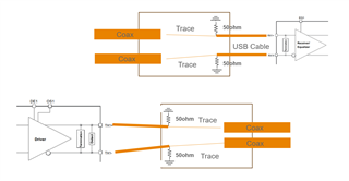
we are laying out a test board for our specialized connector. in testing the TUSB522p, we terminated both rx and tx with 50ohm resistor single-endedly to have an open eye in our testing. questions below

1. the TUSB522p's block diagram shows terminations  built-in the chip. why does it still need external 50 ohm termination

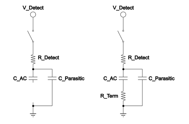
2. what is the resistance range of this termination

3. why is the differential 90 external termination doesn't work.

thanks

bin

  • Bin

    USB3 transmitter implements the receiver detection circuit (Far_end RX Detect). Below is a simplified block diagram from the USB3.2 spec.

    The transmitter correctly detects whether a load impedance equivalent to a DC impedance Rrx-dc is present. The Rx detection operates on the principle of the RC time constant of the circuit. This time constant changes based on the presence of the receiver termination (R_Term). In the figure above, R_Detect is the implementation specific charging resistor. C_AC is the AC capacitor that is in the circuit only if R_Term is also present, otherwise, only C_Parasitic is present.

    For TUSB522P, it will only turn on its corresponding RX termination when its transmitter detects the Rrx-dc of a source or sink. In essence, it propagates the source or sink connection status from downstream to upstream, or from upstream to downstream. It also prevents the source/sink from sending the LFPS until the connection has been established between the source and the sink and going into the compliance mode when not receiving LFPS after 300ms. 

    The external 50ohm termination mimics the presence of Rterm and therefore turns on the TUSB522P, and then in turn, turns on the source.

    Thanks

    David