This thread has been locked.

If you have a related question, please click the "Ask a related question" button in the top right corner. The newly created question will be automatically linked to this question.

TUSB8041: Initial operation struggles

Part Number: TUSB8041

Hi, I am currently fault finding our TUSB8041 circuit which is mostly based on your TIDRBT8 reference design. 
Checked all the usual stuff, but i cant seem to get any sort of connection to the hub from my windows pc. 
Studying the design layout, i do think i may have issues with the stackup and possibly the tracking routes - however i would have thought it should still work with USB2.0 at least? Are there any initial checks or things i have missed? 
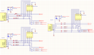
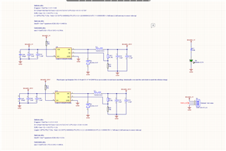
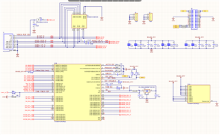
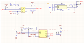
See attached screen shots on my schems for reference... PS, i already noticed and corrected the incorrect polarity on the upstream data lines!
Many thanks in advance - Anthony 
  • Hi Anthony:

        I didn't see issues in schematic, so the hub can not be detected by PC host?

        Please follow the following procedure to check first.

    (+) [FAQ] TUSB8041A: Debug procedure if TI TUSB80xx or TUSB40xx hub can not be detected by USB host - Interface forum - Interface - TI E2E support forums

    Regards

    Brian

  • Thanks for the reply... correct the hub isnt detected by the host. 
    I will run through the debug procedure now. 
    Many thanks again - Anthony 

  • Hi Brian, Please see my replies below

    1: Check power on reset sequence waveform for 3.3v ,1/1v and GRSTz pin and see if  it meets hub power on reset sequence timing   

                   Could you elaborate on this please? Or is it something documented in the datasheet somewhere? Thanks 

    2: Check voltage on USB_VBUS pin and see if the voltage is around 0.5v

                    The voltage here is 0.49v

    3: Check if the crystal is oscillating  after upstream port is connected to host
                    the xtal is oscillating but is very noisy actually... best measurement output frequency i can get is somewhere between 200 and 300khz. so i guess the issue roots from there. Any ideas why this would be? The xtal, its caps and the 1M ref resistor all are present and correct. 

    4: Do not enable SMBUSz with a pulldown unless a SMBUS host is used, otherwise the hub will hang waiting for configuration
                    this pin is left floating - the resistor r5 is not fitted (voltage is measuring approx 3.3v)

    5: Do not connect SDA/SCL to an on-board I2C bus unless it will be used

                  these pins are not currently connected to anything 

    6: Do not leave blank EEPROMs connected to the hub if not used, the hub will enter a programming mode.

                 no eeprom connected 

    7: Please make sure the  layout incorporates the thermal pad as shown in the datasheet.

                yes i believe it to be correct as per the datasheet 

  • For Q1: GRSZz should be low for 3ms after 3.3v and 1.1v stable

    Q3: Crystal clock should be 24Mhz,200k is not right.

      Can you take 1.1v 3.3v  and GRstz waveform?

    Regards

    brian

  • bingo. Looks like i had a dodgy batch of xtals. Many thanks for the point in the right direction. Kindest regards - Anthony