This thread has been locked.

If you have a related question, please click the "Ask a related question" button in the top right corner. The newly created question will be automatically linked to this question.

TCAN1146-Q1: Configuring nINT pin to get an interrupt on WUF to wake MCU

Part Number: TCAN1146-Q1

Hey,

I'm using TCAN1146 on a project that requires to wake up MCU with a classic CAN bus frame. So far, I was able to follow SLLA521B Application Note and get the selective wake-up working, meaning I can get the TCAN1146 from sleep mode to standby mode and CANINT triggering with WUF with the configuration shown below.

SW_CONFIG_4 = 0x00;

// Setup nINT
SDO_CONFIG=0x01
PIN_CONFIG= 0x18 // nINT configuration selection : 11b = Wake Request


// Clear and configure interrupt masks


INT_1=0xFF
INT_2=0xDF
INT_3=0xA1

INT_ENABLE_1=0x40
INT_ENABLE_2=0x00
INT_ENABLE_3=0x00
INT_ENABLE_CANBUS=0x00


//------Selective Wake Config--------------------------------------

//Write desired WUF ID

SW_ID1 = 0x00;
SW_ID2 = 0x00;
SW_ID3 = 0x04;
SW_ID4 = 0x8C;


//Write ID mask

SW_ID_MASK1=0x00
SW_ID_MASK2=0x00
SW_ID_MASK3=0x00
SW_ID_MASK4=0x00
SW_ID_MASK_DLC=0x00

SW_CONFIG_1=0xD0


SW_CONFIG_3 = 0xFE
SW_CONFIG_4 = 0x80

MODE_CNTRL= 0x81

I need help with configuring nINT pin to get a low pulse on interrupt to wake the MCU. So far I have made the above configuration and still, I can't see the interrupt pulse on nINT. Also, I noticed that the SDO/nINT line is low when the nCS pin is high.

below i'm sharing the before and after WUF detection states of a few registers.

INT_GLOBAL Register before WUF

INT_GLOBAL Register after WUF

INT_1 Register after WUF
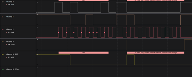
MODE_CNTRL Register before WUF
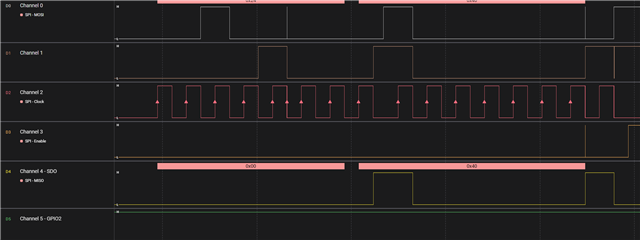
MODE_CNTRL Register after WUF

I really appreciate it if anyone could help me with this.

Thanks.

  • Imesh,

    Thanks for posting! We will likely need until about Tuesday morning CDT to get back to you.

    Best,

    Danny

  • Hey ,

    Thanks for your response. I hope you will be able to help me with this.

    I am waiting to hear from you.

  • Hi Imesh,

    Most of our team is out today, they will likely get back to you tomorrow.

    Sorry for the delay.

    -Bobby

  • Hi Imesh,

    Your configuration here looks correct. I don't see any step that is missing in order to have the nINT signal assert when the CANINT interrupt is set from a WUF. 

    When pin 6 is configured for nINT operation, this pin will output the inverted OR status of all enabled interrupts while the nCS signal is high. This means that the nINT signal will assert low whenever any enabled interrupt is set to 1. When all enabled interrupts are cleared, the nINT signal will be in a high impedance state, so an external pull-up source to Vio will be needed on this signal line. When nCS is asserted low, the pin returns to SDO mode and will be in a push-pull state depending on the data being shifted out by the SPI controller. 

    The SPI responses shown here look expected. Both pre-WUF scope shots show that the global interrupt is cleared (0) and the device mode is in sleep mode. The second scope shot shows that some interrupt in INT_1 (which includes CANINT) is set after the WUF. The forth scope shot actually also shows value of INT_1 and confirms that it is bit 6 (CANINT) that is set in this case. 

    I believe you may have some glitches showing up in your logic analyser that are not being picked up by be transceiver and MCU in this test. The values listed on the screen here are not consistent with what values are reported by the transceiver or what seems to be the desired MCU output. Note that the up-arrows on the clock signal appear in various placed throughout the capture and short glitches can be observed in some other signals. 

    Can you please capture the nINT signal and CAN signal (RXD of the transmitting node if the analog signal cannot be measured) to show the relation between these signals? What I expect to see is nINT assert after the second CAN frame appears on the CAN bus (or RXD pin of any active node). Please ensure that the nINT signal has a pull-up source so that the open-drain output can operate correctly.

    Let me know if you have any more questions while conducting futher testing.

    Regards, 
    Eric Schott 

  • Hey ,

    Thanks for your response. I had an issue with pull-up on nINT. Now the nINT is in logic high level and pulling down when the WUF is detected.

    To get the nINT pin back to logic high level, should we clear the all enabled interrupts?

    Thank you.

  • Hi Imesh,

    I'm glad to hear that the pull-up is helping get more expected results here!

    Yes, in order to clear the nINT status, all enabled interrupts should be cleared. This is done by writing a 1 to the corresponding bit field in the interrupt register. 

    Regards, 
    Eric Schott