This thread has been locked.

If you have a related question, please click the "Ask a related question" button in the top right corner. The newly created question will be automatically linked to this question.

TPD12S521: TPD12S521DBTR || by default configuration without I2C TO ENBLE || HDMI ||

Part Number: TPD12S521

HDMI_PDF.pdf

Hi Team,

We are using the HDMI TPD12S521DBTR in our design. I am unable to detect HDMI and 5V. Please see the attached schematic for reference.
  For communication, we are using NVidia jetson nxn processor  to TPD12S521DBTR.
Below is a query:: -
1. Does the TPD12S521DBTR IC  require configuration through I2C to enable the HDMI??
2. Is there any by-default configuration without i2c to detect the HDMI? (if it is possible, please share documents .)
I am looking for your positive response.
--
Thanks & Regards
RAHUL RAI
Sr. Hardware Engineer (R&D)
+919667738712 | rrai@iotechworld.com
IoTechWorld Avigation Pvt Ltd
Plot No. 31,34 Sector 35
Gurgaon, Haryana 122004
  • Hi Rahul,

     The device does not need configuration.  It provides ESD and backdrive protection, but has no active of configurable circuitry

    Are you able to measure the 5V_OUT pin of the TPD12S521 with no HDMI connected.  This voltage should be at 5V as long as LV_SYPPLY is present.

    This is where to start with your debug and we can work from there.  HDMI won't connect without this voltage.

    Regards,

    Chuck

  • Hi Chuck,

    I am getting 5V_OUT With respect to  LV_SYPPLY = 1.8V without connecting HDMI.

    below is logs with and without hdmi  same

    1.541655] tegradc 15200000.nvdisplay: disp0 connected to head0->/host1x/sor1
    [ 1.541772] tegradc 15200000.nvdisplay: DT parsed successfully
    [ 1.541811] tegradc 15200000.nvdisplay: Display dc. (ptrval) registered with id=0
    [ 1.545919] tegradc 15200000.nvdisplay: vblank syncpt # 8 for dc 0
    [ 1.545928] tegradc 15200000.nvdisplay: vpulse3 syncpt # 9 for dc 0
    [ 1.548745] tegradc 15200000.nvdisplay: hdmi: invalid prod list prod_list_hdmi_board
    [ 1.548755] tegradc 15200000.nvdisplay: hdmi: tegra_hdmi_tmds_range_read(bd) failed
    [ 1.552295] tegradc 15200000.nvdisplay: probed
    [ 1.553020] tegradc 15200000.nvdisplay: fb registered
    [ 1.553647] tegradc 15210000.nvdisplay: disp1 connected to head1->/host1x/sor
    [ 1.553676] tegradc 15210000.nvdisplay: parse_dp_settings: No dp-lt-settings node
    [ 1.553742] tegradc 15210000.nvdisplay: DT parsed successfully
    [ 1.553772] tegradc 15210000.nvdisplay: Display dc. (ptrval) registered with id=1
    [ 1.553920] tegradc 15210000.nvdisplay: vblank syncpt # 11 for dc 1
    [ 1.553929] tegradc 15210000.nvdisplay: vpulse3 syncpt # 12 for dc 1
    [ 1.563505] tegradc 15210000.nvdisplay: probed
    [ 1.563839] tegradc 15210000.nvdisplay: fb registered
    [ 1.567431] tegradc 15210000.nvdisplay: blank - powerdown
    [ 13.349534] tegradc 15200000.nvdisplay: blank - powerdown
    [ 13.349552] tegradc 15210000.nvdisplay: blank - powerdown

  • Rahul,

    The 5V output is a simple regulator that has a built in current limit.  There is no disable switch function.  If there is 5V on 5V_SUPPLY then there will be 5V on 5V_OUT with a dropout of 150-200mV.  This path has a current limit of 55mA to meet the HDMI SPEC, but does not have a disable function.

    The TPD12S521 is a pass through ESD device.with integrated level shifting.  There is no controlled function on the device.

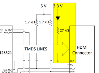
    I did look further at your schematic and there is a missing pull-up and DIODE

    Please review this BOM requirement because it is likely the cause of your issue.

    Regards,

    Chuck

  • Chuck ,

    I have tired with pull-up and schottky diode configuration. Still I am not able  to detect HDMI. 

    Same logs are coming.

  • I'll wait for the logs to see how best to proceed with debug.

  • which logs???

  • Hello Rahul,

    1. The datasheet shows a 27k resistor pull up to 3V3 on CEC_OUT, but I see a 1.69k pull up to 5V on your schematic.
    2. R108, R103, and R105 should be 47k resistors.
    3. R107 should be a 100k resistor.

    Please update your BOM as recommended by Chuck. 

    BR,

    Seong