This thread has been locked.

If you have a related question, please click the "Ask a related question" button in the top right corner. The newly created question will be automatically linked to this question.

TCAN1043A-Q1: TCAN1043A-Q1 pin define issue

Part Number: TCAN1043A-Q1
Other Parts Discussed in Thread: TCAN1145EVM, TCAN1043AEVM,

Hi, Support Team

schematic as below chart: have any concern?
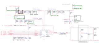
Q1: About “WAKE” pin normally how to application this pin?(used for what?)

    1. I only can image, a mechanical if can provide voltage transition will trigger that device wake-up, right?
    2. The “WAKE”  detection “H”(“L”) to “L”(“H”) (VHmin = Vsup-2V, VLmax = Vsup-3.5V) divider from Vsup.
    3. How to design “WAKE” pins parallel capacitor? Datasheet is 22nF. But EVM is 0.01uF. Which is better?

Q2:How to selection common-mode chokes?

TCAN1043A’s EVB(TCAN1043AEVM) is selection 100uH. But TCAN1145’s EVB (TCAN1145EVM) is 51uH.

    1. Follow EVB selection value for choke?
    2. How to select the value of choke for that CAN bus ?
    3. And I also found the application report “SLLA271”.
  1. Can I refer to "Table 1 (Table 2)" part numbers to select?
  2. In general, what are the chances that a resistor can be used instead of the chock?( Evaluate for choke co-layout with resistor.)

Q3: about TCAN1043A-Q1

Follow IC block diagram. Can delete below pin’s reserved ex-pull-down resistors?

  1. nFAULT
  2. nSTB
  3. En

Follow IC block diagram. below listed pins need ex-pull down resistors?

      1. INH – Pull-down 100k ohm
      2. WAKE – follow Q1

      note: Common Mode Chokes in CAN Networks: Source of Unexpected Transients

       https://www.ti.com/lit/an/slla271/slla271.pdf?ts=1712561886478&ref_url=https%253A%252F%252Fwww.google.com%252F

      if any suggestion, Please advise me.

      Thanks,

      Best regards,

      Lawrence

      • Hi Lawrence,

        I don't have concerns on the schematic. It looks good to me. 

        Q1: About “WAKE” pin normally how to application this pin?(used for what?)

          1. I only can image, a mechanical if can provide voltage transition will trigger that device wake-up, right?
          2. The “WAKE”  detection “H”(“L”) to “L”(“H”) (VHmin = Vsup-2V, VLmax = Vsup-3.5V) divider from Vsup.
          3. How to design “WAKE” pins parallel capacitor? Datasheet is 22nF. But EVM is 0.01uF. Which is better?

        a. This is correct, see 8.4.1.5.2 in datasheet.

        b. What's the question here?

        c. Which EVM are you referring to? TCAN1043A EVM? Actually there is no factory-included capacitor on WAKE pin of TCAN1043A EVM. The typical application case for the wake pin has it used with a pushbutton circuit. Because such fast pull-down sources can cause unwanted transients, a capacitor is recommended to smooth this transition. If the WAKE pin is unused, no capacitor is required on the pin as no transitions are expected on this signal line. 22 uF or 10 nF doesn't really matter.

        TCAN1043A’s EVB(TCAN1043AEVM) is selection 100uH. But TCAN1145’s EVB (TCAN1145EVM) is 51uH.

          1. Follow EVB selection value for choke?
          2. How to select the value of choke for that CAN bus ?
          3. And I also found the application report “SLLA271”.
        1. Can I refer to "Table 1 (Table 2)" part numbers to select?
        2. In general, what are the chances that a resistor can be used instead of the chock?( Evaluate for choke co-layout with resistor.)

        1. a. Yes you can use it as a reference. Usually we recommend 50~100 uH.

           b. Depends on how much common mode noise on the bus. If 100 uH is not enough, using higher value may help, but as the app note described, there may be unexpected transients.

        c. 1. Those are only "examples". You can choose whatever part number you like. TI doesn't make common mode choke.

           2. I'm not sure about replacing CMC with resistor, because there's already termination resistors on CAN bus. In the case of co-layout with terminations, ensure place the CMC between transceiver and the termination resistors, which can realize the best performance. (It is correct on your schematic)

        Q3: about TCAN1043A-Q1

        Follow IC block diagram. Can delete below pin’s reserved ex-pull-down resistors?

        1. nFAULT
        2. nSTB
        3. En

        Follow IC block diagram. below listed pins need ex-pull down resistors?

            1. INH – Pull-down 100k ohm
            2. WAKE – follow Q1

            Yes, nFAULT doesn't need pulldown. nSTB and EN has internal pulldown so external pulldown is not necessary.

            INH can add a pull-down for fast transition.

            WAKE as I described above, it is usually used with a switch. 

            Let me know if you have more questions.

            Regards,

            Sean