Hello,
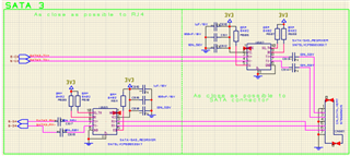
We are experiencing some issue with this schematic :

It works well with SATA Gen2 3Gbps but a lot of errors in SATA Gen3 6Gbps.
This PCB is placed between a ComExpress board and a SATA SSD (cable + rack).
I now there is some capacitors missing on RX lanes, but on the datasheet 10nF is used for ac coupling, while on the evaluation board 100nF is used.
The SATA rev3.3 say 12nF max.
Can someone say why there is 100nF on the evaluation board?
Am I overthinking it? Does it just works better with 100nF? Or a mistake?
Thanks !

