Part Number: TCA9617A
Other Parts Discussed in Thread: TCA9548A
Dear TI Team:
We have IC-TCA9617A in our design, In datasheet it highlights"allowing two buses of 550pF to be connected in an I2C application."
1. It means A side can meet 400pF standard requirement and B side can meet 550pF bus capacitance. Right?
2. Could you explan How TCA9617A can meet 550pF requirement, which parameters are the main factor to guarantee TCA9617A to meet 550pF?
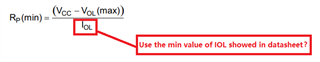
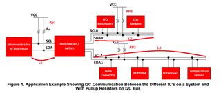
3. How to set the pull up resistor value at B side, because if the resistor is too low which cause the bus will not be pulled low?
Best Regards
Lisa