This thread has been locked.

If you have a related question, please click the "Ask a related question" button in the top right corner. The newly created question will be automatically linked to this question.

DP83867CS: Differences between DP83867CSRGZ and DP83867ERGZ

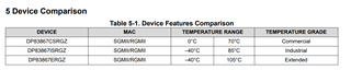
Part Number: DP83867CS
Other Parts Discussed in Thread: DP83867E, , DP83867ERGZ-R-EVM

Hi Team,

We are considering changing from DP83867CSRGZ to DP83867ERGZ as a PHY part.
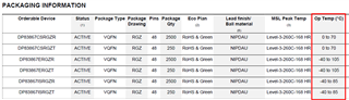
When I checked the difference in the data sheet, there was a difference between the operation temperature and PMD OUTPUT.
Please tell me the following points.

[question 1]
Are there any differences between the DP83867CSRGZ and DP83867ERGZ other than the operating temperature and PMD OUTPUT?

[question 2]
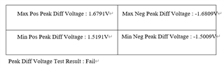
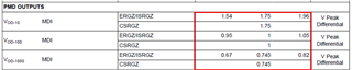
There was no MIN/MAX specification for VOD (Vpeak Differential) of DP83867CSRGZ in the data sheet.
Does this mean that the VOD (Vpeak Differential) output varies because there are no guaranteed MIN/MAX values on the data sheet?

[question 3]
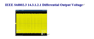
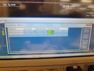
The data sheet states that the MIN/MAX value of VOD (Vpeak Differential) of DP83867ERGZ is from 1.54[V] to 1.96[V].
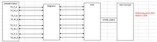
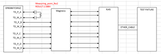
Where is the point where the above differential voltage value is specified?
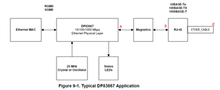
Please tell me the specified points in the diagram below.
Is it the A point of PHY output? Or is it the B point at the RJ45 end? Or is it the C point at the ETHER_CABLE end?

Best Regards,

  • Hi User,

    Thank you for your query, I believe you have found all of the answers you are looking for! As a quick summary, the DP83867 comes in two main flavors: 867& 867R

    The S means that this version supports SGMII & RGMII for the MAC interface, the R version only supports RGMII. 

    Within those two main versions are temperature ratings: Commercial, Industrial, and Extended (only for the S version).

    The PMD outputs for all versions of the DP83867 are the same, however the 867E version has min/max values because it is tested more stringently where we can guarantee them. This output refers to point A in your diagram.

    Regards,

    Alvaro

  • Hi Alvaro,

    Thank you for answering.
    I have a question about what you answered.
    Please tell me about the following.

    [question 4]
    I heard that the regulation for the MIN/MAX values of VOD (Vpeak Differential) for the DP83867E is Point A.
    However, when conducting an ETHER compliance test, I think the test will be performed by connecting an external transformer, RJ45, ETHER cable, etc.
    Therefore, we believe that it will be attenuated by several mV.
    If the MIN value was adjusted at the output end of the DP83867E above, I think the peak differential voltage test would fail due to variations in the PHY components.
    Will parts adjusted to the above MIN value be delivered?

    [question 5]
    I heard in another thread that the amplitude of the differential voltage (VOD) from CHANNELA to CHANNELD is adjusted individually in the process.
    In the case of 10BASE-Te, are the differential voltage (VOD) values of C, I, and E products set to an average value of 1.75V?

    [question 6]
    I heard that the regulation for the MIN/MAX values of VOD (Vpeak Differential) for the DP83867E is Point A.
    Could you please tell me the test circuit at that time?

    Best Regards,

  • Hi User,

    4. Yes this is the case. I didn't want to confuse you before, but points A, B, and C will be the same. I chose A because that is where the output of the PHY is. The DP83867 is a robust ethernet PHY that is compliant with the 1000Base-T standard, it will pass the compliance test.

    5. Yes

    6. No, I'm afraid this is not readily available information.

    Regards,

    Alvaro

  • Hi Alvaro,

    Thank you for answering.
    I have a question about what you answered.
    Please tell me about the following.

    >The DP83867 is a robust ethernet PHY that is compliant with the 1000Base-T standard, it will pass the compliance test.
    >The PMD outputs for all versions of the DP83867 are the same,
    >however the 867E version has min/max values because it is tested more stringently where we can guarantee them.
    The reason for posting this question is that we measured the Peak Differential Voltage of 10BASE-Te with the DP83867CS product.
    However, the result was 1.532V, resulting in FAIL. (Measurement system: Figure 1)
    <Specified value: within 1.540V~1.96V>

    Therefore, we terminated the PHY's PAIRA output end with AC coupling and 100Ω, and measured the Peak Differential Voltage waveform.
    The above measurements exclude transformers, connectors, etc. (Measurement system:Figure2)
    However, the Peak Differential Voltage result at the PHY output end was 1.588[V].
    Also, PMD OUTPUT did not reach the average value of 1.75[V]

    [question 7]
    The result of Peak Differential Voltage at the PHY output end was 1.588[V] instead of about 1.75V.
    If I need to guarantee 1.54V on the test fixture side, I thought 1.588V might be low.
    Is this value a normal output voltage value?

    [question 8]
    You answered, "Because the 867E version has min/max values and is more rigorously tested to the extent that we can guarantee it."
    Based on the above, we believe that there is a possibility of improvement by changing from DP83867CS to DP83867I or E products.
    Do you think the above will improve if you change from DP83867CS to DP83867I or E products?
    Or, will the result remain the same even if I change the parts?

    Best Regards,

  • Hi User,

    I discussed this with my team and all versions of the DP83867 have the same VOD limits. Switching between a CS/I/E product won't guarantee better VOD performance.

    Is this query related to this one? My next response was going to suggest Reg 0xA0 & A1

    https://e2e.ti.com/support/interface-group/interface/f/interface-forum/1343001/dp83867cs-10base-te-compliance-test-peak-difference-voltage-result-fails/5145034?tisearch=e2e-sitesearch&keymatch=%252520user%25253A431079#5145034

    Regards,

    Alvaro

  • Hi Alvaro,

    Thank you for answering.
    Please tell me about the following.

    >Is this query related to this one? My next response was going to suggest Reg 0xA0 & A1
    yes. This thread is about what we asked.
    We have also confirmed that changing the 0xA0 register can improve the issue.
    However, due to the following concerns, we have not determined whether changing the VOD will cause any problems.

    1.Concerns
    (1)10/100/100BASE signals are also affected.
    (2)Only 1.588V is output for 1.75V (TYP) adjustment.
    (3)I checked the description of 10BASE-Te VOD (Vpeak Differential) in the datasheet, but the MIN/MAX values for CSRGZ are not listed.

    Please tell me about the following.

    [question 8]
    The result of Peak Differential Voltage at the PHY output end was 1.588[V] instead of about 1.75V.
    If I need to guarantee 1.54V on the test fixture side, I thought 1.588V might be low.
    Is this value a normal output voltage value?
    Why is the VOD output not 1.75V?

    [question 9]
    I checked the description of 10BASE-Te VOD (Vpeak Differential) in the datasheet,
    but the MIN/MAX values for CSRGZ are not listed.
    Also, since it only outputs 1.588V compared to the 1.75V (TYP) adjustment, I am concerned that there may be variations in VOD.
    Are there any parts shipped whose VOD output is adjusted below the MIN value of 1.54V or above the MAX value of 1.9V?
    Could you please tell me the fluctuation range of CSRGZ's VOD?

    Best Regards,

  • Hi User,

    I don't have any data about the fluctuation range of the CSRGZ's VOD. What I can do is get a few 867EVM's and check their VOD outputs and see how much they vary in lab. I can do this tomorrow, will this help?

    Regards,

    Alvaro

  • Hi Alvaro,

    Thank you for answering.

    >What I can do is get a few 867EVM's and check their VOD outputs and see how much they vary in lab.
    >I can do this tomorrow, will this help?
    yes. Very helpful. Thank you.
    Also, if possible, could you please tell me the VOD output value and the values of the A0 and A1 registers when acquiring data.

    Best Regards,

  • Hi User,

    Sure thing, please allow me until the end of the week to complete this.

    Regards,

    Alvaro

  • Hi User,

    Please find my results below. I also provide the test setup to confirm with yours. All of the EVMs I tested have the DP83867E on it.

    ___________________________________________________________________________________________________________________________

    Setup:

    The scope Ethernet Compliance program on the scope was set to 10Base-T with the Acquisition set to Sample and Energy Efficient set to yes.

    The ethernet cable was connected to the TC6 section of the compliance board, with the jumper on 100Ω for the load.

    Note: With Acquisition set to Average, very low values came from the test. Very similar to the ones you are currently seeing.

    Figure 1 - Configure 10Base-T Settings

    Figure 1 - 10Base-T Scope Settings

    Figure 2 - Compliance Board Connection

    ___________________________________________________________________________________________________________________________

    Test Results:

    Passing Criteria: 1.54V - 1.96V

    Board #1: 1.76 & -1.78

    A0 = 0708 ; A1 = 0609

    Board #2: 1.7 & -1.72

    A0 = 0606 ; A1 = 0707

    Board #3: 1.74 & -1.78

    A0 = 0807 ; A1 = 0606

    ___________________________________________________________________________________________________________________________

    With the correct setup, all boards passed and meet the data sheet spec. Please try with the setup I used to see if this helps you.

    Regards,

    Alvaro

  • Hi Alvaro,

    Thank you for answering.
    Please tell me about the following.

    >Note: With Acquisition set to Average, very low values came from the test.
    >Very similar to the ones you are currently seeing.
    Thank you for the measurement.
    Does that mean that the TEXTONIX oscilloscope also gave very low values when setting acquisition to average?
    Also, are you saying that you got the same results as the KEYSIGHT oscilloscope?

    [Question 8]
    Could you also share the results of setting Acquisition to AVERAGE?

    >With the correct setup, all boards passed and meet the data sheet spec.
    >Please try with the setup I used to see if this helps you.

    We conducted an ETHER compliance test with a KEISIGHT oscilloscope.
    However, the KEISIGHT oscilloscope did not have a function to change the Acquisition from AVERAGE to SAMPLE.
    Therefore, we also conducted tests on a TEKTORONIX oscilloscope.
    However, the result was the same as the KEYSIGHT oscilloscope, and the MIN side failed.

    1.TEST RESULT
    (1)Positive
    ・MAX POS PEAK DIFF VOLTAGE:1.6791V:PASS
    ・MIN POS PEAK DIFF VOLTAGE:1.5191V:FAIL

    (2) Negative
    ・MAX NEG PEAK DIFF VOLTAGE:-1.68091V:PASS
    ・MIN NEG PEAK DIFF VOLTAGE:-1.5009V :FAIL

    Therefore, please let me know the following information.

    [Question 9]
    Regarding the measurement of DIFF VOLTAGE, due to the requirements of the standard, the Peak setting must be tested with the Max-Min setting.
    This is also stated in the TDET3 procedure manual as follows.

    Based on the above, please tell me the settings for Peak in the SELECT field below for the DIFF VOLTAGE test.

    [Question 10]
    Could you please share the above test results in a report file?
    I would like to confirm the following contents.

    Best Regards,

  • Hi User,

    The settings I had for Average were giving me low VOD readings, some as low as 0.9V. Several boards also read ~1.52V, which is just below the minimum passing requirement. I did not save the reports when I ran the test in Acquisition Mode: Average. I would have to go re-run the test. I believe the setting used for Peak was MAX, again I would need to go back and re-run the test to verify. Please allow me another day to return this report to you.

    In the mean time, is there a way to change the way the scope Averages the waveform? If we can make it average the minimum amount of samples, this could make the difference for this test.

    Regards,

    Alvaro

  • Hi Alvaro,

    Thank you for answering.
    We will answer below.

    >I believe the setting used for Peak was MAX, again I would need to go back and re-run the test to verify.
    Regarding the above matter, please confirm it.
    We are waiting for the measurement results.

    >In the mean time, is there a way to change the way the scope Averages the waveform?
    >If we can make it average the minimum amount of samples, this could make the difference for this test.
    sorry. We don't know how to measure with AVERAGE because we have only measured with sample settings.
    Could you please check with the measuring device manufacturer?

    Also, since I will be away on vacation starting next week, I will respond after May 7th.

    Best Regards,

  • Hi User,

    Please find the results below.

    Acquisitions set to Sample: 

    Acquisitions set to Average (# of Waveforms = 64):

    Regards,

    Alvaro

  • Hi Alvaro,

    Thank you for answering.

    In the above results, you have set the peak setting to MAX.
    Regarding the measurement of DIFF VOLTAGE, due to the requirements of the standard, the Peak setting must be tested with the Max-Min setting.
    Please attach the result of setting the Peak setting to MAX-MIN.

    Best Regards,

  • Hi User,

    Sure, I ran the test again with the Min/Max selected and acquisition set to Sample

    Regards,

    Alvaro

  • Hi Alvaro,

    Thank you for answering.
    From the peak differential voltage results of the DP83867E evaluation board, it was found that there was no margin on the MIN side.
    Also, I found that the result is no margin on the MIN side, similar to ours.
    Please tell me about the following.

    【question10】
    Please tell me the number of the board used in the above test.

    >4. Yes this is the case. I didn't want to confuse you before, but points A, B, and C will be the same.
    >I chose A because that is where the output of the PHY is.
    >The DP83867 is a robust ethernet PHY that is compliant with the 1000Base-T standard, it will pass the compliance test.
    >I discussed this with my team and all versions of the DP83867 have the same VOD limits. Switching between a CS/I/E product >won't guarantee better VOD performance.

    【question11】
    You said in your answer to [Question 4] that points A, B, and C are the same.
    The Peak Differential Voltage result of the above DP83867E evaluation board shows a result of 1.75 (MAX), not the adjusted result of 1.75 (TYP).
    I think the cause is that the VOD is adjusted to 1.75 (TYP) in POINTA.
    Why is pointC not 1.75 (TYP)?
    Is the above understanding correct?

    【question12】
    The Peak Differential Voltage results for the DP83867E evaluation board above showed that there was no margin on the MIN side.
    Therefore, I think that even if you switch from CS products to I/E products, you cannot expect to improve 10BASE VOD performance.
    Therefore, we believe that the only way to improve this is by adjusting VOD.
    Is the above understanding correct?

    Best Regards,

  • Hi User,

    Please find my replies below.

    【question10】

    I'm not sure what number you are asking about here, I used a DP83867ERGZ-R-EVM

    【question11】

    Forget about the A, B, C point. You yourself have proven within your own setup that A = C when measuring on Board #13. The test fixture is measuring at Point C and the test passed within the limits, 1.54 - 1.96 when set to Max and 1.61-1.75 when set to Min/Max. 

    【question12】

    Where are you seeing no margin? And correct, switching from the CS to E part will not improve the VOD performance.

    Regards,

    Alvaro

  • Hi Alvaro,

    Thank you for answering.
    We will answer below.

    >I'm not sure what number you are asking about here, I used a DP83867ERGZ-R-EVM
    It will be the board number below that you answered.
    _______________________________________________________________________________
    Test Results:

    Passing Criteria: 1.54V - 1.96V
    Board #1: 1.76 & -1.78
    A0 = 0708 ; A1 = 0609

    Board #2: 1.7 & -1.72
    A0 = 0606 ; A1 = 0707

    Board #3: 1.74 & -1.78
    A0 = 0807 ; A1 = 0606
    _________________________________________________________________________________

    【question13】
    I am thinking of changing A0[3:0] to increase the Peak Differential Voltage of 10Base-Te.
    Please tell me how many mV will increase by adding 1 to the value of A0[3:0], which is in design terms.

    Best Regards,

  • Hi User,

    I am not sure how many mV will increase per value of A0. I do not have the bandwidth today to go into lab and check today but please feel free to adjust this register and see the effects it has on the waveform.

    Regards,

    Alvaro