This thread has been locked.

If you have a related question, please click the "Ask a related question" button in the top right corner. The newly created question will be automatically linked to this question.

TUSB8041: Different boards with TUSB8041 require different drive strength configuration resistor -> Issue

Part Number: TUSB8041

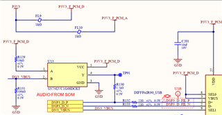
We're facing drive strength issue with TUSB8041 connected devices. Nominally, we've followed 9.53k resistor for USB_R1 as per the recommendation. 

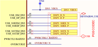
During debugging, we noticed that USB2.0 downstream ports of TUSB8041 weren't getting detected so we've reduced the value of drive strength configuration resistor from 9.53 to 9.05k. In one of the board, 9.05k resistor also didn't work so we went further till 8.55k resistor & it started working. 

We don't have high-end instruments to post figures of measured eye height so we're suspecting following points:

1. The dielectric material's dissipation factor impact on drive strength but at USB2.0 speeds(~12Mbps) it shouldn't impact right?

2. tightly coupled differential lines impacting rise time degradation?

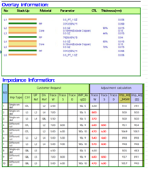
The stackup information is in the below figure(B4SM-> Before stackup modification). The traces are mainly on the top & bottom layers

What could be the main factors which affects drive strength? -> www.ti.com/.../slla429.pdf

  • Hi Santhosh:

        You are going on correct direction. R1 resistor is mainly adjust HS current and open HS eye opening.

       Did you test with HS device and FS device, HS should be 480Mbps.

       For PCB trace impedance, it should target 90 ohm +-10% differential  or 45 ohm +-% for single ended.

       are you able to do TDR to check DP DM impedance  on you board?

    Regards

    Brian

  • Hi Brain, 

    Thanks for the quick response. 

    We're utilising only in FS mode(USB Hub is connected to PCM2903CDB which is compliant to USB revision 2.0, full speed). 

    We've provided guidelines just like this & PCB fab house modified the stackup to achieve the above impedance specs. 

    We don't have TDR instrument(like VNA) to check the practically achieved impedance. Is there any cost effective way to measure impedance?

    Tight coupling of differential traces impacts in losses(We're using 6.8mils width & 8mils seperation microstrip) but will it impact the drive strength & eye opening significantly at USB2.0 full speed?

  • For full speed 12Mbps, PCB trace may not make much difference. can you take full speed package waveform with single ended probe and upload waveform to USBET20 tool to check FS eye diagram?

      You can get USBET20  from USB.org

    Regards

    Brian

  • Hi Brian, I captured USB differential lines using single ended probes but I'm facing an error while uploading the file to USBET20 tool-> "Unknown Exception". 

    If you know any workaround then let me know I'll capture the waveform with short ground length for better waveform & upload here. 

    Or do you know any parameters(Rise time, setup & hole time etc) through which we can analyse in the oscilloscope itself?

    I'm attaching the .wfm file as well so that you can also try once

  • While analysing the waveform, I noticed that the common mode & differential mode voltage won't comply to the USB2.0 specs due to pull-up resistor on the DP line. 

    The PCM2903CDB has recommended a pull-up resistor on the DP line with a AND gate(1st image). Our implementation(2nd at TUSB8041 & 3rd at PCM2903CDB) image which is having yellow in symbols)

    As per specs, we should have common mode voltage of 0.8 to 2.5V( but we're getting more than 3V i.e., (3.37+3.19)/2=3.28V) & differential mode voltage of about 400mV as per my observation on various waveform but ours is 5V!

    I couldn't able to see much info on pull-up resistor importance( Only before POR, it's used for detecting the downstream ports). If it's internal with a switch then it could do but we're providing an external pull-up so will it cause any issues?

  • Did you pullup DP with 1.5k to 3.3v?

    From the waveform , it looks like clock signal, not looks like full speed package.

    Regarding USB20 tool, I will check next Monday to see which format to save.

    Regards

    Brian

  • Hi Santhosh:

        Any update?

    Regards

    Brian

  • Hi Brian,

    As discussed over chat, the pull-up/pull-down is required for USB's LS & FS configuration (https://www.beyondlogic.org/usbnutshell/usb2.shtml#:~:text=Without%20a%20pull%20up%20resistor,has%20a%20SoftConnectTM%20technology)

    I just want to know what are the parameters impacting the driver strength at USB2.0 speeds? 

    Also, any info regarding USB20 tool?

    Regards,

    Santhosh

  • Hi Santhosh:

       For USBET20 tool, please take waveform with CSV format, then load *CSV file to USBET20 tool.

       USB_R1 will affect the drive current on DP/DM which affect the driver strength at USB2.0 speeds.

    Regards

    brian