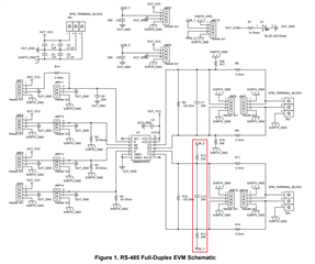
Hello, I'm not very familiar with RS-485 communication, and I'm currently working on a project where I need to implement it to communicate with different MCUs. I'm using the SN65HVD1473 as an RS-485 transceiver. I came across the schematic of the RS-485 Full Duplex evaluation module. I want to know what's the utility of resistors R12, R13, and the capacitor C10 marked in the red rectangle, and should I also include them in my design with the SN65HVD1473? Additionally, should they be placed only between the Z and Y pins or also between A and B?
Thank you for you help!