This thread has been locked.

If you have a related question, please click the "Ask a related question" button in the top right corner. The newly created question will be automatically linked to this question.

DS90UB953-Q1: using BIST for prototyping tests?

Part Number: DS90UB953-Q1
Other Parts Discussed in Thread: ALP

Team,

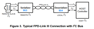
In order to do some system level testing between 953 -> cable -> 954 how can the BIST capability (mentioned in DS section 7.3.4.4 Built-In Self Test) be used?
Do you have a script example (I2C command and sequence) in in order to perform BIST?
or code example you can share?
Does the BIST work together with the pattern generator (ie section 7.6) ?

Can the 953 BIST and pattern generator be controlled over the 954 I2C back channel?
https://www.ti.com/lit/pdf/snla131

Thanks in advance!

Anthony

  • Hi Anthony,

    Thank you for your question. The BIST feature is enabled on the deserializer, once enabled the deserializer will send a signal to the serializer to enter BIST mode. Once in BIST mode the serializer will begin sending a continuous sequence to the deserializer using the operational forward channel speed. This will test the link quality as both the serializer and deserializer will count the errors seen during BIST operation. 

    To enable BIST set register 0xB3 = 0x01 on the 954 and wait for however long you wish to run BIST mode. After the delay, set register B3 = 0x0 on the 954 to disable BIST mode. Register 0x57 of the 954 and register 0x54 on the 953 can then be read to see how many BIST errors were logged during operation. There is an example BIST script available in the 954 predefined scripts within ALP, which I'll attach for you below. Please note that this script includes additional register writes/reads and settings that are not a requirement for BIST mode, but can be used if desired for additional testing. For a simple BIST test only the 0xB3 and respective error logging register reads are necessary. If you'd like additional details on the extra features in this script, you can review this app note starting on section 3.2. 

    The pattern generator can not be used at the same time as BIST. BIST should be enabled from the deserializer so register writes to control BIST would not need to go across the back channel, but for configuring the pattern generator on the serializer, yes the register writes would go across the back channel. Any register reads/writes being sent from the deserializer to the serializer would utilize the back channel.

    ## BIST_953_954_WithForcedError.py
    ##
    ## revision 1.1 June 13, 2017
    ##
    ########
    ######################
    ##
    ## This script file is used to check the link between the 953 and 954
    ##
    ## The Built In Self Test (BIST) generates a puesdo random sequence
    ## and checks for CRC errors between transmitted and received sequence.
    ##
    ## Rev. 1.1
    ## Added Parity Errors, restructured code
    ##
    ##
    ######################
    
    print "\n\n"
    import time
    
    
    #	Define 954 and 953 Adresses
    UB953 = 0x18																#953 SER Alias ID, check 0x5C on 954 for confirmation 
    UB954 = 0x60																#954 Device ID, check 0x00 on 954 for confirmation
    
    #	Port selection, Passthrough, and aliasing
    #board.WriteI2C(UB954, 0x4C, 0x01)											#Enable Port 0 writes
    #board.WriteI2C(UB954, 0x58, 0x5E)											#I2C Pass through Enabled and BC = 50Mbps
    #board.WriteI2C(UB954, 0x5C, 0x18)											#953 Alias defined as 0x18
    
    
    #	Digital Reset except for registers
    board.WriteI2C(UB953, 0x01, 0x01)											#Resets 953
    time.sleep(0.5)
    board.WriteI2C(UB954, 0x01, 0x01)											#Resets 954
    time.sleep(0.5)
    
    print ("Devices Reset")


    #	Confirm Devices can communicate with each other
    print ("954 Device ID (0x00):", hex(board.ReadI2C(UB954, 0x00, 1)))			#954 Device ID, should be 0x7A, check 0x00 for confirmation
    time.sleep(0.5)
    print ("953 Device ID (0x00):", hex(board.ReadI2C(UB953, 0x00, 1)))			#953 Device ID, should be 0x30, check 0x5B for confirmation
    
    print ("------------------------------------------------------------------")
    time.sleep(0.5)


    #	Read Reciever Lock Status
    print ("Reciever Lock Status (0x04):", hex(board.ReadI2C(UB954, 0x04, 0x1)))						#0x04 is DEVICE_STS of 954
    print ("Should read 0xDF")
    
    print ("------------------------------------------------------------------")
    time.sleep(1)


    #	Enable write for Port0 of FPD3_PORT_SEL 
    board.WriteI2C(UB954, 0x4C, 0x01)											#0x4C is FPD3_PORT_SEL


    #	Clear Errors and Error Count
    board.WriteI2C(UB953, 0x49, 0x28)											#0x49 is BC_CTRL. 0x28 selects BIST_CRC ERR CLR and CRC ERR CLR
    
    print ("Read BCC Error Status (0x79):", hex(board.ReadI2C(UB953, 0x79, 1)))	#Clear possible BCC_Error by Reading BCC Error Status
    print ("Consult Register 0x79 on the SER for more information")
    
    print ("------------------------------------------------------------------")
    
    print ("Pre-Error Link Status of 953 (0x52):", hex(board.ReadI2C(UB953, 0x52,1)))					#0x52 is GENERAL_STS of 953
    print ("Should read 0x45 = RX Lock Detect, HS PLL Lock, Link Detect")
    
    print ("------------------------------------------------------------------")
    
    print ("BIST CRC Error count (0x54) on 953 before forced error.", hex(board.ReadI2C(UB953, 0x54, 1)))#0x54 is BIST ERR CNT
    
    print ("------------------------------------------------------------------")
    
    time.sleep(1)


    #	Enabling BIST, Error, and Lock-Change Status
    print ("Read BIST CTL register (0xB3) Before BIST ENABlED", hex(board.ReadI2C(UB954, 0xB3, 1)))		#0xB3 is BIST_CTL, bit 1 controls if enabled or not
    print ("Should read 0x00 or 0x08\n")
    
    board.WriteI2C(UB954, 0xB3, 0x01)											#Enable BIST using BIST_CTL
    
    print ("Read BIST CTL (0xB3) register After BIST ENABLED", hex(board.ReadI2C(UB954, 0xB3, 1)))		#0xB3 is BIST_CTL
    print ("Should read 0x01")
    
    time.sleep(0.25)
    print ("------------------------------------------------------------------")
    print ("Read BIST Lock Status Change of 954 RIGHT AFTER BIST enabled (0x4D):", hex(board.ReadI2C(UB954, 0x4D,1)))		#0x4D is RX_PORT_STS1 of 954
    print ("Read to clear BIST enable Lock Status Change.")
    
    
    #board.WriteI2C(UB954, 0xD0, 0x01)											#Force 1 Error, 0xD0 is PORT_DEBUG register
    
    #board.WriteI2C(UB954, 0xD0, 0x02)											#Force Continious errors, 0xD0 is PORT_DEBUG register
    time.sleep(10)																#Can run BIST for as long as needed
    #board.WriteI2C(UB954, 0xD0, 0x00)											#If forced continious errors, stop forcing errors
    
    print ("Read Post-BIST Lock Status Change of 954 RIGHT BEFORE BIST disabled (0x4D):", hex(board.ReadI2C(UB954, 0x4D,1)))		#0x4D is RX_PORT_STS1 of 954
    print ("Should read 0x03, If lock status changed during BIST, will read 0x13")


    #	Disable BIST and Port0
    board.WriteI2C(UB954, 0xB3, 0x00)											#Disable BIST, using BIST_CTL
    board.WriteI2C(UB954, 0x4C, 0x00)											#0x4C is FPD3_PORT_SEL
    
    print ("------------------------------------------------------------------")
    time.sleep(1)


    #	Check if Error(s) occured
    print ("Post-Error Link Status of 953 (0x52):", hex(board.ReadI2C(UB953, 0x52,1)))					#0x52 is GENERAL_STS of 953
    print "Should read 0x4D = RX Lock Detect, HS PLL Lock, Link Detect, and BIST CRC Error"
    
    print ("Reciever Lock Status (0x04):", hex(board.ReadI2C(UB954, 0x04, 0x1))) 						#0x04 is DEVICE_STS of 954
    print ("Should read 0xDF")
    
    
    print ("------------------------------------------------------------------")
    
    print ("BIST CRC Error count (0x54) on 953.", hex(board.ReadI2C(UB953, 0x54, 1))) #0x54 is BIST ERR CNT
    print ("BIST CRC Error count (0x57) on 954.", hex(board.ReadI2C(UB954, 0x57, 1))) #0x57 is BIST ERR CNT
    print ("Parity Error count MSB (0x56) on 954.", hex(board.ReadI2C(UB954, 0x56, 1))) #0x56 is number of Parity error 8 most significant bits
    print ("Parity Error count LSB (0x55) on 954.", hex(board.ReadI2C(UB954, 0x55, 1))) #0x55 is number of Parity error 8 least significant bits
    
    
    print ("------------------------------------------------------------------")
    
    #print ("953 Device ID (0x00):", hex(board.ReadI2C(UB953, 0x00, 1)))			#953 Device ID, should be 0x30, check 0x5B for confirmation, 
    																				#Usually use this to see if 954 is stuck in BIST mode
    
    #	Clear BIST Errors on 953
    board.WriteI2C(UB953, 0x49, 0x28)											#0x49 is BC_CTRL. 0x28 selects BIST_CRC ERR CLR and CRC ERR CLR
    
    print "\n\n" 																#New line Printed
    

    Regards,
    Darrah