This thread has been locked.

If you have a related question, please click the "Ask a related question" button in the top right corner. The newly created question will be automatically linked to this question.

SN65HVD1785: Not getting complementary signal

Part Number: SN65HVD1785
Other Parts Discussed in Thread: AM26C31, , THVD2410V, THVD2410

Hi everybody,

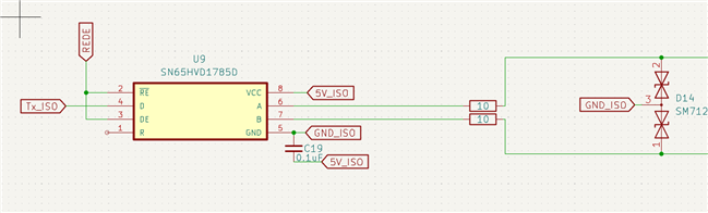
I'm recreating my TTL to RS-422 signal splitter. The first one was created using AM26C31 and works fine. I wanted to make my design more robust, so I chose SN65HVD1785.

Unfortunately it doesn't work as I wanted.  

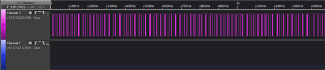
When there is no signal, the input A oscillates instead of being high.

When there's data incoming:
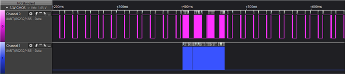
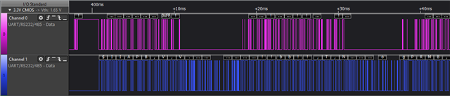
And closer look:

I pulled RE and DE pins to high, so that it can only work in one way - I don't want to get any data, only "broadcast" to another devices for further distances.

Same circuit but with AM26C31 gives me ideal differential output, but doesn't protect my circuit against bus shorts (that's what I really need to have).

Signal that goes to driver pin is 0-5V logic.

What can be wrong about this design? Is there any other possiblity to replace AM26C31 with IC that protects circuit against bus shorts?


Thank you in advance for your answer,

Jakub

  • Hi Jakub,

    First I'd use the THVD2410 instead (in general THVD devices are our best devices for RS-485 type applications) - possibly also the THVD2410V but it may be a bit overkill in feature set for what you need- it is our newer and generally better version of the SN65HVD1785.  It offers equal to improved protection performance compared to SN65HVD1785. 

    Also what color does each signal represent - I am not sure what each signal specifically is - I am guessing the pink signal is "A" but I am not sure about "B". If you could send a picture of "A", "B", and "D" that would be super helpful so I can see the entire signal during transmission. 

    With that being said however I do want to kind of break down what the issue is:

    1. I assume you mean no input signal on "D" and then "A" oscillates - if that is the case then yes, this is possible because a floating "D" input means indeterminate output on A/B - which could include glitching/oscillatory behavior. This can probably be fixed by tying "D" to VCC with a weak pull-up resistor. I am just slightly surprised this wasn't an issue on the AM26C31 device either because the inputs shouldn't be left floating on that device either - it could have been okay - we just don't guarantee it would be in a defined state if "D" is left floating ever. Regardless of what device you go with I'd strongly suggest a pull-up on "D" to ensure that you always have a defined bus state. That being said - it does look like there could be something else problematic with the signal. 

    2. The oscillations during the data transmission look strange - is there any high current or high data rate signals traveling close to the line that could cause interference? Could you also attach a picture of the top of the IC so I can see its markings - I want to trace the part back in our system to ensure it's a legitimate device. Also as I said earlier labeling each signal and if possible showing "D" input and "A" and "B" output would be very helpful to see if there is something off about the incoming signal. 

    3. When you say "protect against shorts" - what exactly do you mean? I am asking because in the strictest sense - all three of the devices in this thread have some form of what would be called short circuit protection - I will say the SN65HVD1785 and THVD2410/THVD2410V are more robust in their protection due to RS-485 requirements + the added fault protection - whereas the AM26C31 is RS-422 which is less robust than RS-485 in general - however I just want to understand what you specifically mean when you want "short circuit protection". 

    So please:

    A) Label scope shots and show "A", "B", and "D" during signal transmission so I can see the entire transmission setup and see if any input signal looks off that could cause this.

    B) A picture of the topside of the  suspect unit that I can see the part markings so I can trace it back into our system

    C) I would suggest to ensure "D" is never left floating - so a pull-up to VCC would be a good idea (4.7k to 10k is the common range)

    D) Clarify what you mean with "short protection" as each device does have some short protection.

    Best,

    Parker Dodson