Part Number: TUSB522PEVM
Other Parts Discussed in Thread: TUSB522P
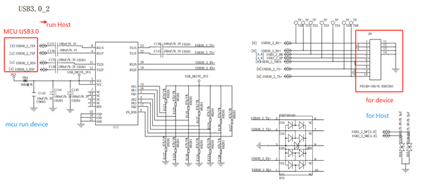
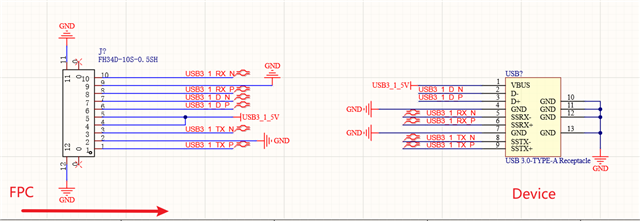
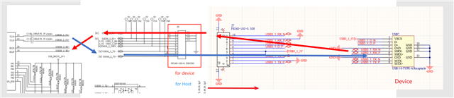
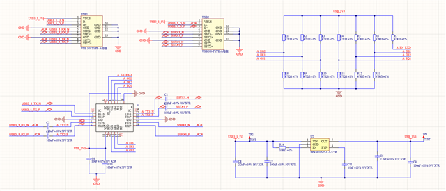
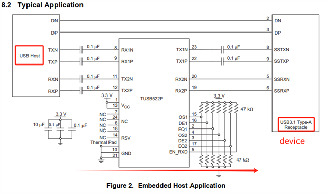
The typical reference schematic design features differential pairs on pins 8, 9, 11, and 12 interfacing with the HOST side's TX (transmit) and RX (receive) channels. Correspondingly, the differential pairs on pins 19, 20, 22, and 23 are linked to the device side's RX and TX channels.
Is it possible, with this design, to interchange the roles of the HOST and device ends?
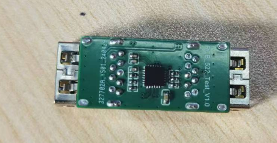
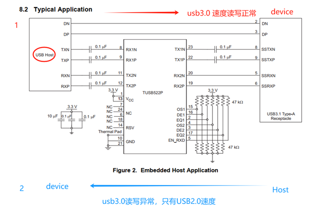
1. Currently, with the reference design, the red section's USB 3.0 speed is normal, but after swapping the roles of the two ends, such as the blue section, the tested USB speed is only that of USB 2.0.
This test was conducted by directly swapping the roles of the two ends without any hardware modifications.
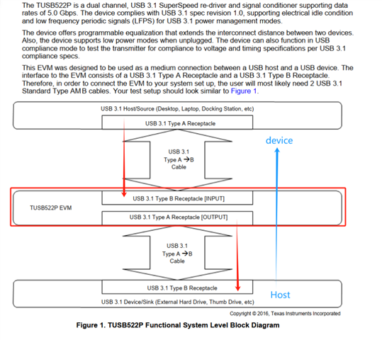
2. In the TUSB522PEVM User Guide, the test topology described only allows for a connection from P1 to P2, with no test results provided for role-swapped scenarios.