This thread has been locked.

If you have a related question, please click the "Ask a related question" button in the top right corner. The newly created question will be automatically linked to this question.

TLIN1431-Q1: Continuous reset signal after VCC(3.3V)-GND short

Part Number: TLIN1431-Q1

I am using the TLIN1431 well, but after shorting VCC 3.3V and GND, the SBC (TLIN1431) continues to generate a reset signal, so the MCU is not working. 

But when I do power on reset, it works fine.

What do you need to add to the initialisation code below?

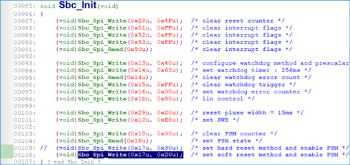
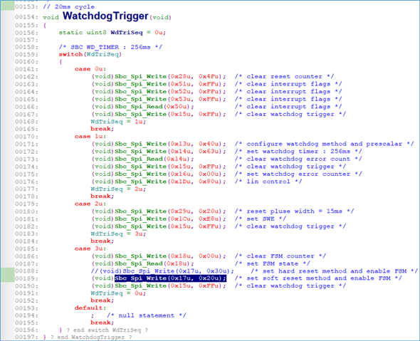
//SBC init fuction//

(void)Sbc_Spi_Write(0x28u, 0x4Fu); /* clear reset counter */
(void)Sbc_Spi_Write(0x51u, 0xFFu); /* clear interrupt flags */
(void)Sbc_Spi_Write(0x52u, 0xFFu); /* clear interrupt flags */
(void)Sbc_Spi_Write(0x53u, 0xFFu); /* clear interrupt flags */
(void)Sbc_Spi_Read(0x50u); /* clear interrupt flags */

(void)Sbc_Spi_Write(0x13u, 0x40u); /* configure watchdog method and prescalar */
(void)Sbc_Spi_Write(0x14u, 0x63u); /* set watchdog timer : 256ms */
(void)Sbc_Spi_Read(0x14u); /* clear watchdog error count */
(void)Sbc_Spi_Write(0x15u, 0xFFu); /* clear watchdog trigger */
(void)Sbc_Spi_Write(0x16u, 0x00u); /* set watchdog error counter */
(void)Sbc_Spi_Write(0x1Du, 0x80u); /* lin control */

(void)Sbc_Spi_Write(0x29u, 0x20u); /* reset pluse width = 15ms */
(void)Sbc_Spi_Write(0x1Cu, 0xE8u); /* set SWE */

(void)Sbc_Spi_Write(0x18u, 0x00u); /* clear FSM counter */
(void)Sbc_Spi_Read(0x18u); /* set FSM state */
(void)Sbc_Spi_Write(0x17u, 0x30u); /* set reset method and enable FSM */

  • Dongwon,

    An engineer has been notified of your post and will respond by end of business 05/10/2024, CST. Thanks for your patience.

    Regards,

    Eric Hackett 

  • Dongwon,

    During a VCC short-to-GND situation, it is expected for the device to follow the procedure outlined in Figure 8-15. However, what do you mean regarding power on reset? Specifically, do you mean you execute a POR while the VCC short-to-GND is still applied? And in this case, do you mean nRST remains high even while VCC short-to-GND is present?

    Also, could you help clarify your desired operation in this case?

    I appreciate the help with these questions. We hope to clear up this for you quickly.

    Best,

    Danny

  • Dear Mr. Danny,


    Sorry, my explanation wasn't clear enough.

    The VCC (3.3V) to GND shorted situation is when the voltage output from the TLIN1431 and GND is shorted. However, removing the shorted condition does not bring it back. The reset waveform attached below remains after removing the short.

    POWER ON RESET is to disconnect and re-inject the input voltage (12V) to the TLIN1431, after which it will behave normally.

     Best regards,

    Dongwon Kim

  • Dongwon,

    Based upon what you've shown, my expectation of what's happening with the device looks something approximately like the following. Please let me know if I misunderstand part of your test setup.

    1. Initial start-up. Initialize TLIN1431-Q1 based upon register settings shown in initialization code above.
    2. TEST: apply external short-circuit between VCC (3.3V output) and GND. Flowchart in Figure 8-15 begins to apply.
    3. VCC < VCCSC for >100µs (tVSC)
    4. TLIN1431-Q1 turns off the VCC LDO.
    5. Because 8'h17[0] = 0b (FSM_DIS), device enters fail-safe mode and FSM_CNTR_STAT now equals 0001b.
    6. Because 8'h18[7:4] = 0000b (FSM_CNTR_SET), the fail-safe mode counter (1) has exceeded the fail-safe mode counter limit (0).
    7. The device executes FSM_CNTR_ACT which is 0011b = Perform hard reset - POR.
    8. The device executes its own POR and all registers are reset to their default values.

    The 171.2ms shown in your oscilloscope plot seems to be corresponding to the initial window watchdog given by tINITWD. This is between 150ms and 200ms.

    In other words, it looks like the device is behaving as I would expect it to behave in this situation. If you desire for it to behave a different way, please let me know what you'd prefer so that I can help adjust the settings to test setup.

    Best,

    Danny

  • Danny,

    Another project using the same code on the same MCU and using a CAN SBC recovers after a VCC(3.3V)-GND Short and the MCU works fine, but this project does not, which is why I'm asking. 

    What needs to be done on the MCU to get the product back to normal after the short is removed?

    Best regards,

    Dongwon Kim

  • Dongwon,

    That's interesting - it could be due to a state machine difference between the components. Which CAN SBC are you using with similar code?

    Regarding your second question, once a hard reset has taken place, the SBC will need to be reinitialized. The device behaves as though power was removed and then applied again. The plot you showed in your post is what would be expected if the device is first initialized and then the watchdog is not serviced.

    However, if you want the TLIN1431-Q1 to avoid this behavior, you could change any of the register settings from the steps shown above. For example, you could change the FSM_CNTR_ACT to a different behavior other than a hard reset (POR) to avoid losing register values. Or alternatively, you could increase the fail-safe mode counter, depending on what you'd prefer.

    Best,

    Danny

  • Danny,

    The Watchdog Trigger (WDI/SDI pin) is being input normally every 20ms, even though it is resetting every 171ms.

    If the reset is still occurring, please contact us to find out how to stop the reset.

    Can you guide me to the register setting code part?

    Best regards,

    Dongwon Kim

  • Danny,

    The next customer milestone is right around the corner, and I need to either fix the issue or explain the content. Please respond quickly

    The request is to stop the reset and allow the MCU to function normally.

    Can you provide any specific guidance on how to handle this or how to fix the code?

    Best regards,

    Dongwon Kim

  • Dongwon,

    After the reset, have you reinitialized the TLIN1431-Q1 by flashing again? When a hard reset occurs, this must take place. Also, can you please confirm the exact state of PIN/nCS during this event?

    Best,

    Danny

  • Danny,

    The reset phenomenon has disappeared. If you can answer our engineer's three queries below (highlighted in yellow), I think we'll be done.

    The phenomenon of repeated reset after "VCCSC, short to ground" occurred disappeared after changing the "FSM_CONFIG Register (17h) FSM_CNTR_ACT" setting to soft reset (0010b) as described above.

    <Q1>  I would like to know if there is any difference in behaviour between the different settings of FSM_CONFIG below.

    - 000b = Disabled

    - 0010b = Perform soft reset

    - 0011b = Perform hard reset - POR

    <Q2> When setting the SBC initialisation as shown in the code above, is there anything I should pay attention to? If there is anything that needs to be modified, please let me know.

    <Q3>To use the SPI control mode's timeout watchdog (256ms), we input the watchdog trigger to the SBC at 20ms intervals as shown in the code above. 

    When I do a watchdog trigger, do I need to re-set the SBC settings every time like the code above? 

    Or can I just set the value of "WD_INPUT_TRIG Register (15h) WD_INPUT" to FFh every time I trigger the watchdog? (ex. (void)Sbc_Spi_Write(0x15u, 0xFFu); /* clear watchdog trigger */

    I would be grateful if you could elaborate on what to watch out for when triggering the watchdog and what you recommend.

    Thanks.

    Best regards,

    Dongwon Kim

  • Dongwon,

    <Q1>  I would like to know if there is any difference in behaviour between the different settings of FSM_CONFIG below.

    - 000b = Disabled

    - 0010b = Perform soft reset

    - 0011b = Perform hard reset - POR

    Soft reset and hard reset are different reset actions that take place. See data sheet section 8.3.22.2 - the relevant information is that the hard reset selection is equivalent to a power-on reset (POR).

    <Q2> When setting the SBC initialisation as shown in the code above, is there anything I should pay attention to? If there is anything that needs to be modified, please let me know.

    Please give me a little more time to parse through and give some feedback here.

    <Q3>To use the SPI control mode's timeout watchdog (256ms), we input the watchdog trigger to the SBC at 20ms intervals as shown in the code above. 

    When I do a watchdog trigger, do I need to re-set the SBC settings every time like the code above? 

    Or can I just set the value of "WD_INPUT_TRIG Register (15h) WD_INPUT" to FFh every time I trigger the watchdog? (ex. (void)Sbc_Spi_Write(0x15u, 0xFFu); /* clear watchdog trigger */

    You only need to reset settings after a POR. Your original post seems to have shown that the device was entering fail-safe mode, and then taking the designated fail-safe action, which you had programmed as executing a hard reset (POR). See below for reference:

    • Initial start-up. Initialize TLIN1431-Q1 based upon register settings shown in initialization code above.
    • TEST: apply external short-circuit between VCC (3.3V output) and GND. Flowchart in Figure 8-15 begins to apply.
    • VCC < VCCSC for >100µs (tVSC)
    • TLIN1431-Q1 turns off the VCC LDO.
    • Because 8'h17[0] = 0b (FSM_DIS), device enters fail-safe mode and FSM_CNTR_STAT now equals 0001b.
    • Because 8'h18[7:4] = 0000b (FSM_CNTR_SET), the fail-safe mode counter (1) has exceeded the fail-safe mode counter limit (0).
    • The device executes FSM_CNTR_ACT which is 0011b = Perform hard reset - POR.
    • The device executes its own POR and all registers are reset to their default values.

    Best,

    Danny

  • Danny,

    Thank you for your cooperation. 

    Now that the issue is resolved, it looks like we just need to check and clean up.

    For <Q3>, I am wondering if it would be okay to put this code only "(void)Sbc_Spi_Write(0x15u, 0xFFu); /* clear watchdog trigger */" in the Watchdog Trigger function.

    Thanks.

    Best regards,

    Dongwon Kim

  • Dongwon,

    After looking through your code I don't see any errors from the initialization you've chosen. The soft reset change (as we discussed) will help maintain the register settings after a fail-safe mode event occurs. Another approach could have been to increase the FSM counter threshold if desired, but this also works fine since the application of the TCAN24xx-Q1 is so selectable.

    And regarding your clarification to <Q3> above, thanks for helping point out what you meant - I might have originally misunderstood. Since your watchdog is configured to Timeout rather than Window, you are able to service it as frequently as you'd like. There should not be an issue with inserting as many triggers as desired.

    Of course, many applications will implement an interrupt service subroutine or some sort of timed thread to ensure the watchdog is being serviced within the appropriate timeout period. It is of course up to your choice how this would be designed in your system.

    Best,

    Danny