This thread has been locked.

If you have a related question, please click the "Ask a related question" button in the top right corner. The newly created question will be automatically linked to this question.

DS90UB941AS-Q1: Pass-through problem in port1 D_GPIO2

Part Number: DS90UB941AS-Q1

Dear TI:


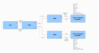
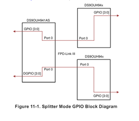
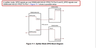
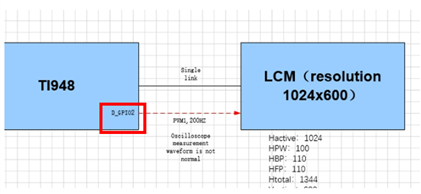
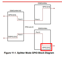
    We used a 941 followed by two 948 pass-through two-channel PWM, and found that the PWM waveform of 941 port0 (GPIO0) pass-through to 948 side was normal, but the PWM waveform of port1 (D_GPIO2) pass-through to 948 side was wrong. Have you ever encountered this kind of PWM?

  • Hi Loki,

    If the PWM of Port 0 works and the PWM of Port 1 does not work, there may be differences in the GPIO setup causing the received signal to be incorrect. Can you confirm the following?

    • Port 0 PWM Frequency
    • Port 1 PWM Frequency
    • Port 0 PCLK Frequency
    • Port 1 PCLK Frequency

    Attached is a script that shows the register configuration for the 941 and 948 GPIOs. Does this match your setup?

    serAddr = 0x18
    desAlias0 = 0x34
    desAlias1 = 0x36
    
    #941 - Port 0 GPIO
    board.WriteI2C(serAddr, 0x1E, 0x1) #Port 0 SEL
    board.WriteI2C(serAddr, 0xD, 0x3) #GPIO0 input
    
    #941 - Port 1 GPIO
    board.WriteI2C(serAddr, 0x1E, 0x2) #Port 1 SEL
    board.WriteI2C(serAddr, 0xE, 0x30) #D_GPIO2 input
    
    #948-A GPIO configuration
    board.WriteI2C(desAlias0,0x1D, 0x5) #GPIO0 output, enable Remote GPIO control
    
    #948-B GPIO configuration
    board.WriteI2C(desAlias1,0x1E, 0x50) #GPIO2 output, enable Remote GPIO control


    Best,

    Jack

  • Dear Jack:

         My configuration is consistent with what you gave, and the pwm frequency on PORT0 and PORT1 is the same, both are 200HZ. We use 941 VCs spliter mode, and the soc dsi packs two signals (VC0 and VC1). The 941 side parses VC0 and VC1 signals to port0 and port1 respectively, and port0 and port1 have the same PCLK, and then connect two 948 channels respectively. Two 948s are connected to two identical screens. The block diagram is as follows:

  • Dear jack:

        The configuration for 948 is a bit different. When I configured 948-B, I set 0x34 to 0x2 and then set 0x1E to 0x50,and the rest is the same.

  • Hi Loki,

    I'll get back with you shortly.

    Best,

    Jack

  • Hi Loki,

    The configuration for 948 is a bit different. When I configured 948-B, I set 0x34 to 0x2 and then set 0x1E to 0x50

    948-B must be configured to use GPIO2 and not D_GPIO2. On the 948 side, D_GPIO is only applicable when in dual link mode. Can you try using GPIO2 instead of D_GPIO2?

    Splitter Mode Operations with the DS90Ux941AS App note: Link

    Best,

    Jack

  • Dear jack:

        But I have learned that port1 of 941 can only use D_GPIO passthrough.And the actual experiment is also the same, port1 of 941 cannot pass through GPIO signal, only port0 can.


  • Hi Loki,

    I do not disagree with the setup of the 941. The setup of the 948-B is where it does not match the app note. The 948-B is currently using D_GPIO2 (Pin 17) as indicated in the diagram. The 948-B needs to use GPIO2 (Pin 10) instead according to the diagram in the app note. Splitter mode is a special configuration for the 941 where the D_GPIO signals on the 941 are routed to the GPIO signals on 948-B.

    User diagram:

    App note:

    Best,

    Jack

  • Dear jack:

        Configuring GPIO2 is now OK, thank you very much.

  • Hi Loki,

    Thank you for confirming. Happy to help!

    Best,

    Jack