This thread has been locked.

If you have a related question, please click the "Ask a related question" button in the top right corner. The newly created question will be automatically linked to this question.

TCA6408A: Project schematic review

Part Number: TCA6408A

Hello:

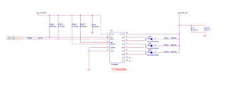
Please assist in conducting a review of the MC project schematic about TCA6408A

Due to the urgency of the project, we hope to receive feedback as soon as possible,Thanks!!!

  • Hey Jimmy,

    We are currently looking into this issue. Our team will respond by E.O.D 5/13.

    Thanks,

    Jack 

  • Looks OK.

    (The two colors have different forward voltages, so with a single resistor, you will not be able to enable both at the same time.)

  • Hi Jimmy,

    I don't see a problem with the current implementation. I am not sure what Clemens is referring to here. 

    Please keep in mind that floating inputs should be pulled HIGH or LOW through a resistor to prevent a floating input and increased ICC current. The other option is to configure those floating pins as OUTPUT. 

    Regards,

    Tyler

  • Hi Tyler:

    Does this floating input refer to the P6/P7 pins? I see the datasheet explanation as shown in the figure below. If the P6 and P7 pins are not used, should they be suspended or pulled down? Please help confirm, thank you!!!

  • Hi Jimmy,

    Floating input is any GPIO pin (Pxx) that is configured to INPUT and does not have any connection to the pin (no load). 

    If P6 and P7 are unused there are a couple of options. The pins can be left open and configured as OUTPUTs through the configuration register, or pull-up/down resistors can be added to the INPUT pins P6 and P7 to keep them biased HIGH or LOW. 

    Regards,

    Tyler