This thread has been locked.

If you have a related question, please click the "Ask a related question" button in the top right corner. The newly created question will be automatically linked to this question.

TPD3S716-Q1: How big is the ringing that occurs in a short-to-battery warranted?

Part Number: TPD3S716-Q1

Hi team,

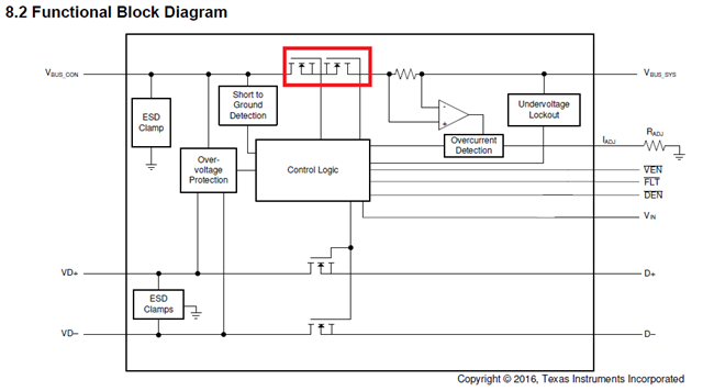
TPD3S716-Q1 guarantees a short-to-battery of 18VDC.

So how big is the ringing that occurs in a short-to-battery warranted?

In the data sheet Fig. 6-10 (P.10), ringing is as much as 40 Vp at a short-to-battery. Is this within the warranty?


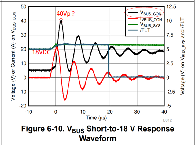
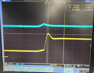
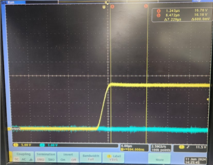
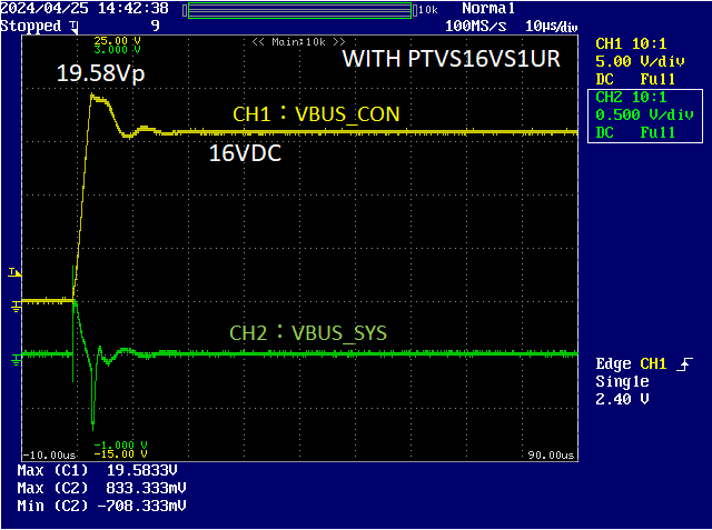
Even with a TVS diode, ringing of 19.58 Vp (at a short-to-battery of 16 VDC) is occurring in my hand.

I want you to guarantee this.

Regards,

Okuyama

  • Hello Yuki,

    The short answer is yes, 40Vp is within the warranty. 

    When voltage on VBUS_CON exceeds the OVP threshold voltage level, it takes roughly (typ) 2us to turn off the FET. When the FET turns off, a ringing of nearly two times the applied DC voltage can be expected. Section 9.2.2.1 in the datasheet goes over methods to take precaution of excessive ringing, such as your TVS diode. 

    Figure 6-10 shows when 18V was applied on the VBUS_CONN pin. So as long as careful capacitor selection is taken or an RC snubber circuit (or TVS diode) is implemented to keep the ringing below 40V, the device will be protected. 18V was used for the OVP test as it is the VBUS_CONN pin's Absolute Maximum voltage rating, but car batteries are usually around 13V.

    BR,

    Seong

  • Hi Seong,

    When the VBUS_SYS pin of TPD3S716-Q1 is 0 V (GND), how big ringing is guaranteed (is it also 40 Vp)?

    In that case, is The waveform of 19.58 Vp (at a short-to-battery of 16 VDC) within the warranty?

    Best regards,

    Okuyama

  • Hello Yuki,

    I'm not 100% sure about this one, so I'll need to test this on the bench and let you know.

    It may take about a week before I can get back to you as I currently do not have an EVM and will need to acquire one first.

    BR,

    Seong

  • Hello Seong,

    Please let me know if there is any progress on the test.

    And, the NMOS (red frame) in the VBUS line, please tell me if there is any information on the withstand voltage (absolute maximum rating) between each terminals.

    Best regards,

    Okuyama

  • Okuyama,

    I have yet to get an EVM, but I should in the next few days.

    Noted on your new inquiry. I will let you know once I have an update.

    BR,

    Seong

  • Hello Okuyama,

    Thank you for waiting. I now have a short to battery tester I can use for the bench test, so I will share my test results this week.

    And I do not have any other data besides than the abs max ratings from the datasheet.

    BR,

    Seong

  • Hello Seong,

    How was the result of the bench test?
    I am looking forward to seeing the result.
    Best regards,

    Okuyama

  • Hello Yuki,

    I just finished the bench test using the TPD3S716-Q1EVM (specifically, using U1, USB1 port, and USB2 port). First, the scope capture below shows when 5V was supplied to VBUS_SYS and 17V was discharged to VBUS_CON from a 22,000uF capacitor. The yellow signal is VBUS_CON and the blue signal is VBUS_SYS. 

    The scope shot below shows the same test but when VBUS_SYS is 0V.

    The scope shot shows that without voltage on the VBUS_SYS pin, there is no ringing.

    BR,

    Seong 

  • Hello Seong,

    Thank you for your reply.
    So, the ringing voltage of the below waveform is generated, is there TPD3S716 problem in terms of guarantee?

    I would like this waveform to be electrically guaranteed.

    For example, if the two NMOS in the TPD3S716 are each rated at 18V, what if the waveform above is a guaranteed voltage?

    Best regards,

    Okuyama

  • Hello Okuyama,

    Yes, it is guaranteed. The short-to-battery protection isolates the internal system circuits from any over-voltage conditions at the VBUS_CON.

    BR,

    Seong

  • Hello Seong,

    Thank you for your answer.

    By the way, could you tell me maximum guaranteed voltage of the ringing at the VBUS_CON due to a short circuit to the battery when VBUS_SYS =0V(GND)? (40Vp?)

    Best regards,

    Okuyama

  • Hello Yuki,

    As long as the VIN pin is supplied with 3.3V to power the Control Logic, it would be the same 40Vp as shown in Figure 6-10. 

    BR,

    Seong

  • Hello Seong,

    Please tell me maximum value of guaranteed voltage at the VBUS_CON of the ringing when VIN pin and VBUS_SYS are 0V(GND).

    Best regards,

    Okuyama

  • Hi Yuki,

    I do not have this data, but I will look into this and get back to you.

    BR,

    Seong

  • Hi Yuki,

    If VIN is 0V or below UVLO, the device is unpowered, so the absolute max on VBUS_CON would be 18V.

    BR,

    Seong


  • Hi,Seong,

    What would happens when the VBUS_CON voltage exceeds 18V when the device is unpowered ?
    Ringing of 19.58 Vp (at a short-to-battery of 16 VDC) was occured in my hand when VIN and VBUS_SYS are 0V(GND).

    Best regards,

    Okuyama

  • Hi Yuki,

    This could potentially damage the device.

    BR,

    Seong

  • Hi,Seong,

    I would like to know why the voltage that the VBUS_CON can withstand changes when the device is not powered(VIN= 0V or below UVLO) and when it is unpowered (VIN= over UVLO).
    If the VBUS_CON exceeds 18V when the device is unpowered (VIN= 0V or below UVLO), what will happen and where will it damage? And why doesn't it damage when the device is powered?

    Is it two NMOS that will be damaged?
    For example, if two NMOS are each rated at 18V, I think the voltage between VBUS_CON and VBUS_SYS(0V) can withstand 32V (18V×2) ringing.

    Best regards,

    Okuyama

  • Hello Okuyama,

    The bottom line is that the absolute maximum rating should never be exceeded. When there is a short-to-18V-VBAT condition on VBUS_CON, our validation tests conclude that ringing up to 40V can be withstood, but only for a short period of time as shown in Figure 6-10.

    What's important to note is that this is guaranteed only under the same conditions, where the device is powered so that the overvoltage is detected and all of the recommended operating conditions are met. Therefore, ensure that your system always follows the recommended operating conditions. Otherwise, the device could be damaged permanently and will be inoperable.

    Exactly what will all get damaged and the degree of damage is unpredictable as it will vary case-by-case. And more importantly, I am unable to answer your questions as there is no damage characterization data I can refer to, or do myself.

    BR,

    Seong