This thread has been locked.

If you have a related question, please click the "Ask a related question" button in the top right corner. The newly created question will be automatically linked to this question.

DS90UB913Q-Q1: DS90UB913Q-Q1

Part Number: DS90UB913Q-Q1

Hello,

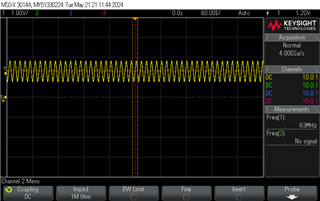
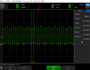
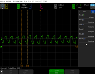
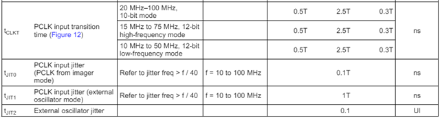
I have a HM1246 Himax imager connected to a DS90UB913Q-Q1 device in 10 bit mode and the PCLK is running at 83 MHz. 

The Iamge sensor get a MCLK via SN74LVC1G17QDCKRQ1buffer and the sensor generate the 83 MHz frequency to the DS90UB913Q

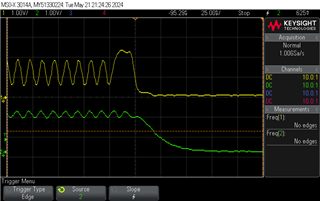
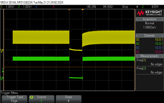
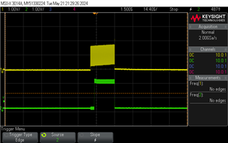
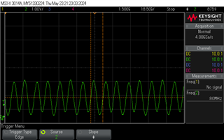
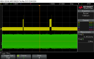
 When the Image is saturation or dark there is a lock but in live video when the data is in all the gray level the lock is not stable and there is no video. on the screen.

Any idea whatcan be the problem?

Roi  

  • Hi Roi, 

    Have you taken a look at the PCLK signal during this change in state? Is there a change in the PCLK frequency? 

    Would you be able to share oscilloscope captures of the PCLK signal and lock? 

    Additionally, would you be able to provide a register dump of the 914 when the issue is being experienced and when it is not (e.g the two modes mentioned)? 

    Best,

    Zoe

  • Hello

    Attached the pclk (Yellow) and the lock (green) signals when there is no lock ( lock is blinking)

    Regarding the registers, I work on it.

    Roi

  • Hi Roi, 

    Would you be able to do some explanation of this material? Is the yellow PCLK in the top right the signal from the deserializer or the serializer? Is there any change to the PCLK signal input to the 913? 

    Best,

    Zoe

  • The all picture is from the Deserializer side.

    Attached the register dump.


    SER_DES_reading.xlsx

    Below is the PCLK from Serializer:

    PCLK_SerializerGrren(PCLK_Serializer)-Yellow(PCLK_Deserializer)

    When the lock is fail the ISC is not working.

    Roi

  • Hi Roi,

    When lock is low, are local I2C transactions not working? If so, this would point to an issue in the power supplies of the UB914. 

    Best,

    Zoe

  • Hello Zoe

    1. What can be the reson that when my sensor not supply the pclk to the DS90UB913Q we mesured 25MHZ pclk on UB914?

    2. The lock is blinking and I can ead from 913/914.  Did you review my ISC registers?

  • Hello Roi,

    The US team is currently out of office due to the US public holiday and will return on 5/28. Thank you for your patience at this time 

    Best Regards,

    Casey

  • Hi Roi,

    There is an internal oscillator on the 914 which may result in the 25MHz measured PCLK. 

    From the register dump, it looks like the 914 is strapped to the wrong mode. If the PCLK is at 83MHz, the 914 should be strapped to 10-bit mode. Would you be able to change this setting? In 10-bit mode, 0x1F[0]=1.

    Best,

    Zoe

  • Hi

    yes , I can change this setting but It is necessary If we are working in default mode when  1F register is '0' ,?

    we config i914 to 10bit by MODE Pin on Deserializer when Rmode Resistor Value is 11K, If need we will change 1F register to '1'

    Roi

  • Hi Roi, 

    To use the UB914 and UB913, they must be in compatible modes. The selected mode will change the forward channel frequency from the 914 to the 913. When using a PCLK of 83MHz, 10-bit mode is required to be used as 12-bit modes only support up to 75MHz. 

    Best,

    Zoe

  • Hi Zoe

    1. We change 1F register to '1':

    *In Live Video - the pclk  is not stable and fall from 83MHz to 50 MHZ and there is no output video

    * In test pattern ( all data is '0' ) there is a good pclk and there is an output video.

    2. 913, Reg 5[2] , we didn't read '1' in bit 2 even we configurate it by resistors.

    3. On the EVB there is a pull down resistors (DIN0-11,HS, VS, PCLK,CLKIN) , It's necessary? 

    4. Atttached the schematic,R51 is not connect in 914 schematic

    Roi

    913.pdfDes914.pdf

  • Hi Roi,

    The register 0x1F should not be 0x00 under proper operation. When in 10-bit mode 0x1F[2] should be 1 to denote it is in 100MHz mode. If the PCLK from the imager is indeed 83MHz, the devices need to be in 10-bit mode. Have you checked the power supplies on the 914 and 913? 

    To properly override the mode of the 914, 0x1F[4] must be set as well. 

    3. On the EVB there is a pull down resistors (DIN0-11,HS, VS, PCLK,CLKIN) , It's necessary? 

    On the pins listed, pull down resistors are not required.

    Best,

    Zoe

  • Hi Zoe

    Yes, we check the power supply on the 914 & 913:

    914: VDD is 1.8V and VDDIO= 3.3V

    913: VDD is 1.8V, VDDIO=3.3V

    As I wrote. I config the 10 bit mode by resistors (10K pull up and 11K pull down resistor) , why I didn't read it when the 914, 0x1F[4]  ='1'?

    -> There is a power up sequence to the registers?

    We config the 913&914 as below:

    913:

    Reg35= 0x04

    Reg14 =0x00

    Reg 5 = 0x20

    914:

    Reg1F = 0x11 

    Roi

  • Hi Roi, 

    On the 913, we would not recommend writing 0x05=0x20 or 0x35=0x04. For register 0x05, the deserializer will configure the 913 mode over the back channel on initialization. When 0x05=0x20, the serializer is preventing this configuration. Can you provide an update once this is removed from the initialization script? 

    Best,

    Zoe

  • Hi Zoe

    Attached our register list.

    0160.SER_DES_reading.xlsxRoi

  • Hi Roi,

    From the register settings I don't see any errors being thrown here. If the issue is still being seen, can you elaborate on when this register dump was taken / what was the procedure doing so? I don't see any loss of lock. 

    If the issue is still being seen, can you please provide a scope capture of the PCLK from the serializer, the PCLK output from the des, and the lock pin on the 914 in the same scope shot? 

    Best,

    Zoe

  • Hi Zoe

    Attached the pclk on 914 and 913.

    Roi

  • Hi Roi,

    It's a little unclear to me what the exact issue is being seen here. 

    What is the difference between the image in saturation and live video? When the image sensor is in saturation is the image sensor on? In live video, is the lock pin still seen to toggle? 

    Would you be able to check the PCLK input is matching our specifications during this state? These can be found below: 

    Please ensure the scope is properly grounded during these measurements as without this may result in some offset/noise. 

    Can you provide measurements for the power pins on the 913 and 914 for voltage and noise? 

    Additionally, would you be able to share the 913/914 layout? This will help us check is layout guidelines are being followed. 

    Best,

    Zoe

  • Hello Zoe

    Thanks for your suppott, The board is working, the problem was on the power pin of the image sensor.

    Roi