


Other Parts Discussed in Thread: DS100BR111,
EQ BOOST settings are the same as the CTLE settings.
I am going to give a more concrete definition of the CTLE gain curves.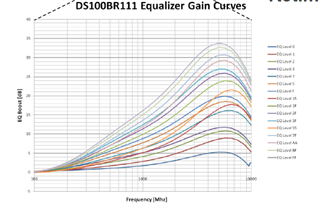
Above are the CTLE gain curves for the DS100BR111. If you look closely, you should be able to see that the y-axis is EQ boost and the x axis is frequency. The gain curves are in various colours depending on the EQ level. Each of the curves are boosted max at the Nyquist frequency, this is the case for all redriver parts with the EQ block included. In the case of the DS125BR111 that is 6GHz at max speed.
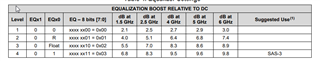
In the table above, the dB value that each data rate and EQ setting indicates is equivalent to the height of the peak of the gain curve. For example, choosing level 4 would mean that you're choosing the EQ curve that has a maximum equalization of ~10dB at it's nyquist frequency 6GHz. The curve would look as it does on the image above with the peak being at 10dB when the freq is 6GHz.
So, the IL variation that can be handled with DS125BR111 without bit errors depends on how big of a swing that IL variation is.
If the IL goes above the peak, then the device is not equalizing enough, so it would need a higher setting. If the redriver is in the middle or there is more than 10 dB from the transmitter of the device to the endpoint, than it is recommended to overequalize a bit.
If the IL goes below the peak, there is a risk of applying too much overequalization that may cut some of the data transmission.
It is important to consider the amount of Insertion loss(IL) a system has when choosing a redriver to purchase. Please review our portfolio at https://www.ti.com/interface/pcie-sas-sata/products.html#1389=PCIe5&
Best Regards,
Nick