This thread has been locked.

If you have a related question, please click the "Ask a related question" button in the top right corner. The newly created question will be automatically linked to this question.

LMH0397: Pins Configuration

Part Number: LMH0397

Good morning,

I am currently working on a new design and I would like to use this component (LMH0397). We will be using a resistor-fixed configuration. Therefore, we have several pins that we will not be using.

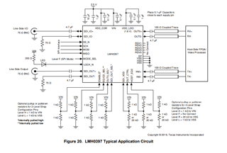
Reviewing the chip datasheet, we have not found any specific note that says what to do with these pins (pullups/pulldowns?). Depending on the pin, we have observed that some have internal pull-up resistors, while others, depending on the configuration, are left floating.

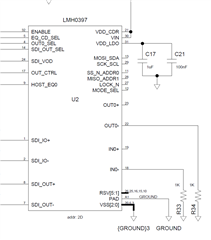
I am attaching a screenshot where you can see the pins that we will not be using. Do you think it is correct to leave them floating?

Thank you very much in advance,

Diego

  • Hi Diego,

    You can leave the unused pins floating if you are not using them. I suggest to use some of the functionality of the retimer if possible. The Lock_N pin is a useful indicator for CDR lock.

    You can refer to the diagram above for connections

    Additionally, your OUT0- and IN0- are terminated with 1k ohm resistors. The trace for each of those 100ohm differential traces can be terminated with 50ohms instead of 1k ohms.

    Best Regards,

    Nick

  • Thank you for your prompt response.

    Unfortunately, due to project requirements and resource constraints, we are unable to implement the additional signals you suggested. While we appreciate the value of your recommendation, we have decided to leave those pins floating.

    We sincerely appreciate your assistance and guidance in this matter.

    Best Regards,

    Diego