Tool/software:
Hi,
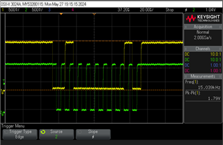
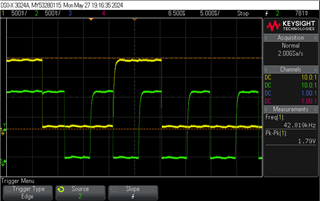
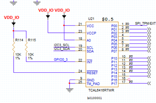
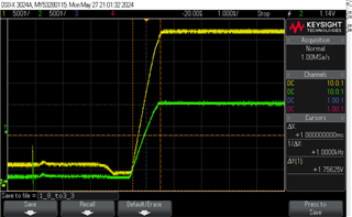
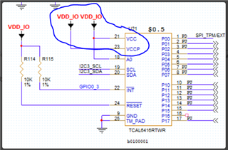
I have a problem accessing the device when VCC is 1.8V and VCCP is 3.3V. See the schematic below:
When VDD_IO is 3.3V there is no problem, When VDD_IO is 1.8V there is no ACK from the device.
Any ideas?
Thanks
Noam
Tool/software:
Hi,
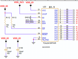
I have a problem accessing the device when VCC is 1.8V and VCCP is 3.3V. See the schematic below:
When VDD_IO is 3.3V there is no problem, When VDD_IO is 1.8V there is no ACK from the device.
Any ideas?
Thanks
Noam