Part Number: MAX3243
Tool/software:
Hi,
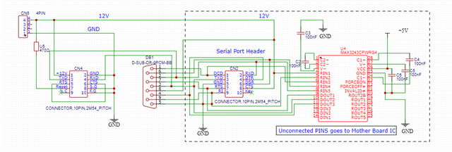
Currently using MAX3243 16pin TSSOP model.
Whether we can connect Rin - pin4 is directly to 12V Supply.
We are using for COM port connections between PC and Card Reader (CTS - Pin8).
Thanks & Regards,
Siba
Part Number: MAX3243
Tool/software:
Hi,
Currently using MAX3243 16pin TSSOP model.
Whether we can connect Rin - pin4 is directly to 12V Supply.
We are using for COM port connections between PC and Card Reader (CTS - Pin8).
Thanks & Regards,
Siba