This thread has been locked.

If you have a related question, please click the "Ask a related question" button in the top right corner. The newly created question will be automatically linked to this question.

DS90UB954-Q1: Sync image fail

Part Number: DS90UB954-Q1

Tool/software:

Dear Sir,

  We try sync mode on 953/954 and we can get the image send by sensor(cable is 10m).

We are transmitting 2560*720@30fps video data, and the Mipi datarate is 1.6Gbps/lane. 

Cable:STP

The images we received are as follows,Sometimes it is normal, but sometimes the video often fail is as follows picture1 & 2.

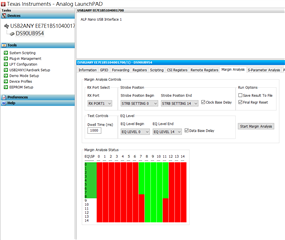
We try running the margin analysis program,the result is as follows picture3.

Can you give some suggestions for improvement?

  • Hello,

    Thank you for reaching out. These MAP results are passing, so there should not be any issues with the link between the 953 and 954. How often do these failure states occur, and is a power cycle necessary to generate a normal video or will re-initializing or performing a soft reset on any of the devices recover the video? Are any errors being seen in the registers? Can you also share what data type is being used?

  • Dear Sir,

     Thank you for your suggestion, I will confirm the CRC register value.

    Can you help confirm whether the design of the 954 peripherals on the circuit diagram is correct.

    C15,C35,C50,C51,R29,R31

  • Hello,

    Overall, this schematic looks good. The chosen AC capacitors (C18, C35, C50, and C51) are proper for operating in CSI Synchronous mode, which is what the mode pin is strapped to. As long as the mode is not overridden with the registers, these capacitor values are not an issue. A few minor notes on the schematic:

    • The 1.5k pull-up resistors on the I2C line are slightly low, however, if there is no indication that I2C communication is failing this is not a concern
    • Recommend verifying that the chosen oscillator and ferrite beads on the power pins meet the requirements in section 7.4.4 and 8.2 respectively
    • The third inductor in the PoC network has a different placement than the data sheet example network
  • Hi Sir,

      When the image was abnormal, I checked the TI954 register value.

    The register 0x4D is 0x03 --> 0x33.

    How can I check this issue?

  • Hello,

    Register 0x4D = 0x33 indicates that lock has been lost at some point since the last read of the register and a CRC error has occurred on the forward channel. From the screen shot register 0x4E = 0xED indicates that several errors are occurring (unstable line length, line length and count change, encoder errors, and CSI errors). It seems like the data on the forward channel is being impacted, this could be due to the cable quality/connection, an external interference, or even the PoC network.

  • Hi Sir,

     How do I debug POC network issues. Could it be caused by POC power noise?

  • Hello,

    The simplest way to investigate POC would be to test the system using a bench supply to power the deserializer and serializer separately (remove the POC component from the system) and see if the issue persists.

    There are limitations for allowable noise on the POC, this app note includes details on noise requirements as well as how to measure the noise of a specific system.

  • Hi Sir,

      Could you provide email to me,I want send the circuit and layout file,double check again.

  • Hello,

    Has there been any changes to the 954 schematic that was previously shared? Are both the 953 and 954 being used in your system custom boards? 

    Can you also share some more information about the issue you are seeing?

    • How often does the failure state occur?
    • Is a power cycle necessary to generate a normal video or will re-initializing or performing a soft reset on any of the devices (imager, serializer, deserializer, SoC, etc.) recover the video?
    • Does a hard reset on any of the devices  (imager, serializer, deserializer, SoC, etc.) recover the video?
    • What data type is being used?
    • Does powering the system without the PoC network (local supply power) resolve the issue or decrease frequency of the issue?
    • The 954 schematic shows that both RIN ports are being used, are both 953s receiving the same resolution (2560*720@30fps)? 

    Can you also share a full register dump? In the previous screenshot there was a lost lock and several errors logged.

  • Hi Sir,

    • How often does the failure state occur? --> It usually occurs when the system is turned on.
    • Is a power cycle necessary to generate a normal video or will re-initializing or performing a soft reset on any of the devices (imager, serializer, deserializer, SoC, etc.) recover the video? --> System isn't restart 
    • Does a hard reset on any of the devices  (imager, serializer, deserializer, SoC, etc.) recover the video?
    • What data type is being used?
    • Does powering the system without the PoC network (local supply power) resolve the issue or decrease frequency of the issue? --> Remove POC power the issue is same.
    • The 954 schematic shows that both RIN ports are being used, are both 953s receiving the same resolution (2560*720@30fps)? -->1920x1080 raw

    follow as ,  AC coupling caps to RIN pins traces the impedance value is differential 100ohm or single-end 50 Ohm?


  • Hello,

    Can you clarify and answer the other questions from the previous post?

    • Can you quantify how often the failure state occurs? Is the state seen 50% of the time, or is it seen more or less often.
    • What do you mean by “system isn’t restart”. Is it not possible to reinitialize the system or perform a soft reset? To perform a soft reset on the serializer and deserializer simply write to register 0x01 = 0x01. The imager should have a similar register that can be written to for restarting or stopping and starting the stream.
    • Does a hard reset on any of the devices (imager, serializer, deserializer, SoC, etc.) recover the video?
    • What data type is being used?
    • For the received resolution of the 953s, one device is receiving 2560 x 720 @30fps and the other is receiving 1920 x 1080. Is this correct? What are the fps of the second device? If only one imager is streaming at a time, doe the issue occur?

    The RIN traces should be loosely coupled with 50 Ohm impedance on each trace

  • Hi Sir,

        What is the impedance (ohms) of the PCB trace from the RIN PIN to the AC CAP?  Differential 100 ohm or single-end 50 ohm?


  • The RIN traces can be routed as 100 ohm impedance differential traces up to the AC coupling capacitors. After the capacitors, the traces must be routed as 50 ohm impedance single-ended traces.

  • Hi Sir,

     Thanks for your reply. Can you help check the inductance on the Poc ?

    L1~L6 Is the inductance value correct?  1500ohm = Murata BLM18HE152SZ1

    The frame loss problem has not been solved yet.

  • Hello,

    These inductors appear to be the same listed in the datasheet examples and have an appropriate inductance. Note that the 50ohms impedance needs to be maintained on the connection between the high speed trace and POC as well.

  • Hi Sir,

     The inductance values ​​on the 953 POC is 47ohm/330ohm/1500ohm and 954 is 1500ohm POC are different, will this affect the FPD_LINK transmission data?  Will it affect the transmission and sometimes the frame data will be dropped?

    Andy

  • The PoC network does not have a specific number of inductors or inductance value that must be used. There are various inductors that can be used to create a PoC network, the datasheet provides a few examples. Any changes to the inductors of those examples could impact how the network performs. What is important to the FPD-Link devices that utilize the PoC network is that there is a high impedance and low insertion and return loss on the channel. The examples have been tested to meet these requirements, so any modifications would need to be validated to ensure that there is not any changes to the performance. The inductor vendors are able to provide more details on how different inductors may behave in a network as they are the ones who designed the PoC networks. However, you mentioned earlier in this thread that removing the PoC network did not have any impact on the system so the PoC issue does not seem to be related to any issues in the system. Is this not actually the case, has something changed?

  • Hi Sir,

     How many frames can be dropped in 1 second from TI953 to TI954?

    When TI954 receives data have loss, how to confirm whether it is TI953 loss or sensor loss?

  • The 953 and 954 do not operate with a set number of frames over a given time period. The 953 has registers which count and check the data for errors (ex: registers 0x5C  - 0x64). If the 953 is detecting data with errors then that likely means that the errors occurred between the sensor and the serializer or the sensor itself. If these registers do not detect data with errors then the errors are likely occurring downstream on the fpd-link interface, the 954, or 954 to SoC/display CSI interface.