This thread has been locked.

If you have a related question, please click the "Ask a related question" button in the top right corner. The newly created question will be automatically linked to this question.

DS90UB933-Q1: DS90UB933-Q1

Part Number: DS90UB933-Q1

Tool/software:

Hi,

I am currently using an DS90UB933-Q1 Serializer and Camera with our ECU and DS90UB934-Q1 Deserializer.

My goal is to create a tap for this unit that will collect the camera data but not interrupt the ECU control.  I see that both DS90UB960-Q1 and DS90UB964-Q1 have the dual output option and work with the DS90UB933-Q1 Serializer.  Can you tell me which of these components will be best for just the purpose of splitting and the signal with my current chipset?

Thanks,
Ian

  • Hello,

    Thank you for your question. The 960 and 964 are similar devices and could both be used for this purpose. One difference between the two is the supportable modes, the 960 is able to support CSI and RAW modes of operation, while the 964 will only support RAW mode. The best option for your system will depend on the mode that is to be used by the devices, which is not currently clear in the block diagram.

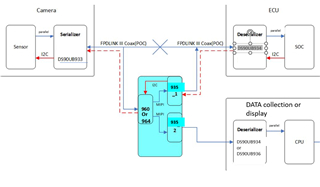
    However, there are some compatibility issues with your block diagram. The 960 and 964 deserializers have a MIPI CSI interface, while the 933 serializer and 934 deserializer have a parallel data interface. In your current block diagram, the sensor is sending MIPI CSI data to a 933 serializer, and the 934 deserializers are incorrectly labeled as transmitting MIPI CSI data to the SOC/CPU. If this is not a typo and MIPI CSI data is desired, the parallel interface 933 and 934 will not be compatible with this system architecture. Additionally, the 960 or 964 deserializer that is to be used in the tapping board highlighted in blue, will output MIPI CSI data, which will not be compatible with the receiving 933 serializers. If MIPI CSI data is desired, MIPI CSI serializers such as the DS90UB35 or DS90UB953 paired with a MIPI CSI deserializer such as the DS90UB936 or DS90UB954 should be used instead.

  • Hi Darrah,

    Thank you for the clarification, I must use the DS90UB935 or 953 in the splitter circuit for MIPI conversion.  The Data sheet shows DS90UB935 & 953 is compatible with the DS90UB34 (I am stuck with 934).  Are there any compatibility issues I should know about such as I2C or POC?

    I tried to fix the diagram.  Project is to tap/split into our current ecu/camera system without interrupting ECU communication.  We will then record or display data on second channel.

    Thanks

  • Hello,

    There are a few considerations when pairing a MIPI CSI serializer (935/953) with a parallel deserializer (934). Ensure that the serializer is programmed to operate in DVP mode (only 10-bit or 12-bit HF are available 12-bit LF is not available). This mode will allow the serializer to operate in a manner that is compatible with the 934 parallel interface. This app note includes additional considerations and details. The I2C functionality will be the same as the 933 to 934 pairing (using proper I2C addresses/alias for each device on the bus, pull-up resistors, etc.). The POC guidelines will also be the same but note that the chosen POC must be able to support all frequencies across the entire FPD-Link channel (back channel and forward channel) for a respective serializer - deserializer pair. A 933 to 934 pairing could potentially have different frequencies than a 935/953 to 936/954 pairing. Some POC networks will be able to cover the frequencies for both pairings, but not all, so verify the network being used for each pair in your system is suitable for that specific pair. This app note includes more details on choosing a suitable POC network.

    One minor note on the updated diagram, for the "DATA collection or display" the 934 to CPU interface is correct, just note that if a 936 is used instead the interface will be MIPI.