This thread has been locked.

If you have a related question, please click the "Ask a related question" button in the top right corner. The newly created question will be automatically linked to this question.

DS125MB203: HDMI skew and jitter

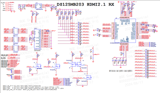
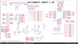
Part Number: DS125MB203
Other Parts Discussed in Thread: TMDS1204, TDP1204

Tool/software:

Hi,

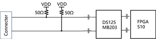
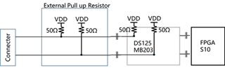
 We used ds125 in a HDMI design . In HDMI 4K , we need test skew(about 112ps for every line) and jitter(about data lines 500KHz;clock lines 10 MHz),have you done this test before ?

Best Regards

Young Hui 

  • Hi Young Hui,

    Here are skew and jitter specs provided in the datasheet.

    Best,

    Lucas

  • Thanks for your reply.

    Let me explain our issue in detail:

    The following is our design schematic. We are using DS125MB203 with Altera S10 for HDMI 2.1 connection, the hardware design is following <AN 952: Intel® Arria® 10 and Intel® Stratix® 10 HDMI 2.1 System Design Guidelines>. We are doing the HDMI CTS(Compliance Test Specifications).

    The design principle can be simplified as

    I understand this connection is based on CML mode of Tx driver.

    In HDMI CTS standard, there is the requirement that in the power-off mode the terminal impedence of HDMI input should be infinite. But in this connection mode, the measured impedence is 100Ohm.


    In order to pass this requirment, we change the pull-up resistors to 500Ohm. But with this connection, in the HDMI TMDS test mode, the signal can not be recognized by DS125, mo matter how we tune the EQ/DEM etc., .If we change the pull-up resistors from 500ohm to 250ohm, the signals can be recognized and the inter pair skew and jitter test also passed by tuning EQ with FF, only 150mV min swing test failed.


    It seems that the terminal impedence is not matched well and cause the poor signal quality. But how to satisfy the terminal impedence requirment both in power-off mode and the power-on mode?

  • Hi Young Hui,

    If the RESET pin of DS125MB203 is pulled high, the device is put in low power mode and receiver inputs are high impedance. Alternatively, individual channels can be powered down with SMBus register writes. Can this be used to solve the impedance issue in power-off mode?

    • 0x02[0]=1 // override RESET pin
    • 0x01=___ // power down individual channels

    FYI the schematic images you shared are quite small/low resolution and I cannot see any schematic connections.

    Best,

    Lucas

  • I reupload the schematic again, thanks

  • Dear Lucas,


    Thank you very much for your adive. Let me add explanation of our issue.

    For HDMI CTS standard, in power-off mode, the terminal impedence of HDMI input is infinite. In power-on mode, the terminal impedence of HDMI input is 100Ohm.

    In DS125MB203 datasheet, we find that the inputs have on-chip pull-up 50Ohm resistor. So the system diagram is like this:

    Here is the problem, In this design(the recommended design by Intel), In power-on mode, the measured input impedence are 50Ohm (two parallel connected 100Ohm).

    And we found that by increasing the external pull up resistors, the VCM is drifted (For example VCM=2.0V with 240Ohm external pull up resistors)

     We think since DS125 already has on-chip 50Ohm resistor, there should be no need to add the external pull up resistors.

     Can we redesign the system like this?

    What’s the risk by using the DC coupled structure?

    Or is it possible to disconnect the on-chip pull-up resistor in DS125MB203?

     And we will try your suggestion that by pull-high the reset pin and override the reset pin after power-on to match the power-off impedence.

  • Hi Young Hui,

    Thank you for sharing the schematic again. I'm looking into this and will get back to you by COB today.

    Best,

    Lucas

  • Hi Young Hui,

    Here is the problem, In this design(the recommended design by Intel), In power-on mode, the measured input impedence are 50Ohm (two parallel connected 100Ohm).

    The receiver impedance of DS125MB203 is 50 ohm single-ended, 100 ohm differential. So I believe this should meet the HDMI requirement of 100 ohm differential.

    What’s the risk by using the DC coupled structure?

    AC coupling is required on the DS125MB203 to ensure no DC voltage reaches the device. Therefore the DC coupled structure should not be used.

    Or is it possible to disconnect the on-chip pull-up resistor in DS125MB203?

    Yes this is possible, however we typically don't recommend doing this. I'm still struggling to understand, what is the issue in power-on mode in this setup? Is the impedance not 100 ohm differential? How would disconnecting the on-chip pull-ups resolve the issue?

     And we will try your suggestion that by pull-high the reset pin and override the reset pin after power-on to match the power-off impedence.

    To clarify, my recommendation is to pull the reset pin high OR override the reset pin with register writes. I see on your schematic that it may be difficult to pull the reset pin high, so overriding with register writes may be easier to implement.

    Best,

    Lucas

  • Hi Lucas,

     I want to know the Pull-Up to VDD resistor in DS125MB203 disign

    Follow blew picture.

  • The receiver impedance of DS125MB203 is 50 ohm single-ended, 100 ohm differential. So I believe this should meet the HDMI requirement of 100 ohm differential.

    Because there are both external 100 ohm differential  and on-chip 100 ohm differential, they are parallely connected. So the measured total differential impedence is 50 Ohm, and also ,with external 100ohm differential, in power-off mode, the measured differential impedence will not be infinite.

    To clarify, my recommendation is to pull the reset pin high OR override the reset pin with register writes. I see on your schematic that it may be difficult to pull the reset pin high, so overriding with register writes may be easier to implement.

    By override the reset pin with register wirtes, when power-off ,the register setting still works?

  • Hi Young Hui,

    The internal pull-up resistors on receiver inputs are 50 ohm.

    Because there are both external 100 ohm differential  and on-chip 100 ohm differential, they are parallely connected. So the measured total differential impedence is 50 Ohm, and also ,with external 100ohm differential, in power-off mode, the measured differential impedence will not be infinite.

    I believe your understanding here is incorrect. Internally, the receiver pins have 100 ohm differential impedance. The external traces need to also have 100 ohm differential impedance to match the internal impedance. The internal and external pull-up resistors do not combine parallely. The original design shown is correct and maintains 100 ohm differential impedance.

    Regarding power-off mode: is it possible to turn off your external VDD supply? This will allow external differential impedance to become infinite.

    By override the reset pin with register wirtes, when power-off ,the register setting still works?

    I'm not sure I understand the question here, so let me clarify.

    • If you mean, will the register settings still work when individual channels are powered down by overriding the reset pin? The answer is yes.
    • If you mean, will the register settings still work when the DS125MB203 device is powered off? The answer is no, register settings will get reset.

    Now that I have a better understanding of your system and concerns, I'm not sure this method will work to achieve infinite impedance in power-off mode, since there will still be external pull-ups. I think you will need to turn off your external VDD supply.

    Best,

    Lucas

  • I believe your understanding here is incorrect. Internally, the receiver pins have 100 ohm differential impedance. The external traces need to also have 100 ohm differential impedance to match the internal impedance. The internal and external pull-up resistors do not combine parallely. The original design shown is correct and maintains 100 ohm differential impedance.

    I have different opinion that the termination resistors are only used to match the transmission line impedance. In this case, the internal pull-up resistors work as termination resistors, there is no need to add another external pull-ups. And we do MEASURED the 50Ohm from the test equipment (Keysight9505A). It confused us.

    In DS125 datasheet, there is no external pull-ups needed in application.

    We also lookup the TMDS1204 application which is the standard HDMI redriver. And there is no external resistor needed. (No idea why intel recommends DS125 in HDMI application, it drives us crazy)

    If you mean, will the register settings still work when the DS125MB203 device is powered off? The answer is no, register settings will get reset.

    This is what I mean, then when power off mode, the register setting is wiped out. We can’t maintain infinite input impedance of DS125MB203.

    What if we use DC coupled application? The DS125 will not work correctly? I think it is our last hope.

  • Hi Young Hui,

    DS125MB203 was not designed to be used in HDMI applications, this is why it's necessary to use external pull-up resistors for HDMI applications. Unfortunately AC coupling is required on the receiver of the MB203.

    I believe we have released some passive muxes since the Intel reference design was created which may be better suited for HDMI applications. Allow me to check with my colleague on specific part numbers and get back to you early next week.

    Best,

    Lucas

  • Hi Lucas,

    Thank you. Our HDMI application need to support 4K/8K resolution and 8bit/10bit datawidth. So we need passive mux which can support both TMDS and FRL mode, the speed requirements are 3G/6G/8G/10G/12G.

    P.S. I just lookup the TI product list. It seems that the maximum speed can only reach 6G. If there are higher speed passive muxs, please let me know.

  • Hi Lucas,

    DS125MB203 was not designed to be used in HDMI applications,

    Is there any reference design case that apply TMDS1204/TDP1204 with intel S10/A10 FPGA to realize HDMI application?  If there is one, please let us know the detailed information. Thanks.

  • Hi Young Hui,

    Thank you for sharing your application's specific requirements. We may have a passive mux which can support this use case. I am discussing with a colleague and will get back to you soon.

    Unfortunately TI does not have any reference designs implementing TMDS1204 or TDP1204.

    Best,

    Lucas

  • Hi Young Hui,

    We have a new passive mux which can support your application and will be released very soon. I can share an advance information datasheet with you via E2E private message.

    I sent you an E2E friend request. Please accept so I can message you privately.

    Best,

    Lucas

  • I would like to draw a conclusion to this thread. DS125MB203 was not designed for HDMI applications. When Intel was developing HDMI applications, there was no specialized HDMI retimer yet, so they chose a daughter board adopting DS125MB203. And they admitted that it never pass the HDMI compliance testing (CTS). The main issue of DS125MB203 is that it can only support AC-coupled input, which is not suitable for the DC-coupled input required by the sink of HDMI. As a result, it is very difficult to match the input impedance, leading to relatively poor signal quality, especially in high speed mode. Intel has started to redesign the new retimer solution with TMDS1204 and modify the Design Guide for HDMI application, but it is not clear when it will be done. For those designers who only need to develop the HDMI application demo, you can continue to use DS125 as the retimer. However, if your product needs to pass the HDMI CTS certification, based on our experience, the advice  is: Try other options.

  • Hi Young Hui,

    Thank you for adding your conclusion to this thread. One thing I'd like to clarify is that DS125MB203 is not a retimer, it is a redriver with mux/switch/fanout capability.

    Best,

    Lucas