This thread has been locked.

If you have a related question, please click the "Ask a related question" button in the top right corner. The newly created question will be automatically linked to this question.

SN65HVD3082E: Inquiries on design guide & operation

Part Number: SN65HVD3082E

Tool/software:

Hello experts,

My customer has a few questions on RS-485, could you please share your feedback on below inquiries?

Thank you in advance for your support.

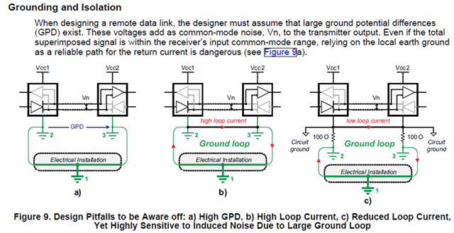
1. Do we have any design guide or materials that cover below topic in more detail?

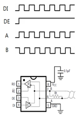
2. Assuming that there's no termination resistor, 

2-A. Is Vpk-pk of pulses A & B same as Vcc?

2-B. Does differential voltage A-B swing from -Vcc to +Vcc?

From datasheet, I would think these would not be the case, but I do not quite understand why...

Thank you.

  • 1. Figure 9 just says that when ground differences exist, you have a choice between a high loop current or higher common-mode noise.

    2. Many driver outputs have series diodes to protect against reverse voltages, so you will not see the full supply voltage on the bus. This is allowed because the RS-485 standard requires the driver to generate at least ±1.5 V over a 54 Ω load; there is no requirement for a higher voltage with a smaller load.

  • Hi Jade,

    1. That is the information we have on ground potential differences and how they apply to RS-485 systems. When we do trainings for RS-485 that is the information we share. There really isn't much more to share beyond the trade-offs of the ground routing in the system - if you have any more specific questions I would be happy to take a look at them. 

    2a) No the voltage at "A" or "B" will not be VCC when there is no termination. This is for two reasons, the first is that there is a diode voltage drop between VCC and output that needs to be considered and the bus itself will draw some current (depending on how many transceivers on the bus - fully loaded bus will have a relatively significant loading so there will be a non-zero mA level current even without termination on a fully loaded bus - but the termination will most likely make the VOD lower)

    2b) Differential voltage is balanced for RS-485 - so a logic 1 and logic 0 should have the same voltage magnitude but opposite polarity (standard allows for up to +/-200mV of difference in logic level magnitude) . So you should expect the same voltage magnitude (within +/-200mV) for both logic low and logic highs. It won't be +/-VCC due to the reasoning in point 2a - there is loss between VCC and output even without termination (diode drop and current being requested at every node on the bus)

    It is important to note that the device doesn't generate signals less than GND w.r.t. to GND. What I mean by that is that if you are transmitting a logic low that means the "B" pin will go high and the "A" pin will go low - the differential voltage (which is measured at  A w.r.t. B) will be negative, but if you took individual voltage measurements at "A" and "B" w.r.t. GND they are both going to be >= GND.

    Please let me know if you have any other questions and I will see what I can do!

    Best,

    Parker Dodson