Tool/software:
Hi, Support Team
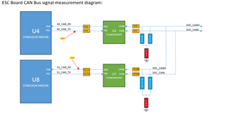
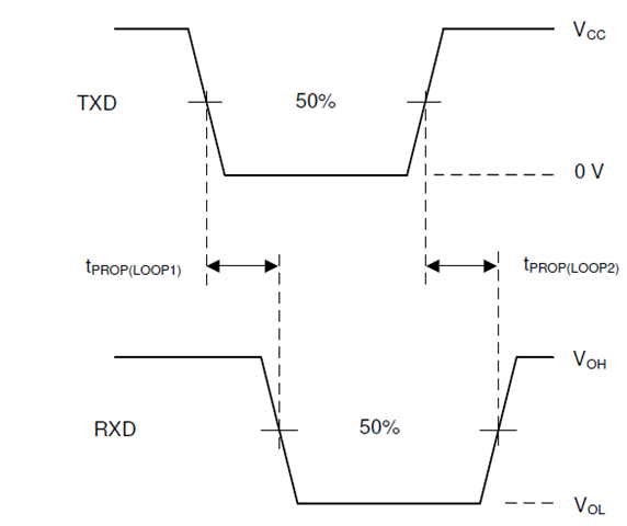
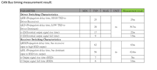
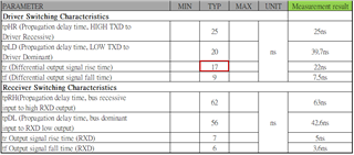
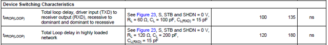
our client use TCAN330 and test CAN Bus timing measurment result as below chart:
about test result have any concern?
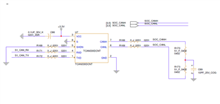
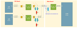
schematic:
if any suggestion, Please advise me.
Thanks,
Best regards,
Lawrence
Tool/software:
Hi, Support Team
our client use TCAN330 and test CAN Bus timing measurment result as below chart:
about test result have any concern?
schematic:
if any suggestion, Please advise me.
Thanks,
Best regards,
Lawrence


 .
.