This thread has been locked.

If you have a related question, please click the "Ask a related question" button in the top right corner. The newly created question will be automatically linked to this question.

TCAN4550: Schematic review

Part Number: TCAN4550

Tool/software:

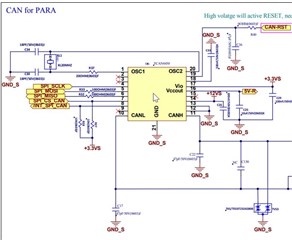
 Please help to review the schematic and below some question. Thanks

1) Are the peripheral circuits and parameters of OSC required for R5? With a 25MHZ crystal oscillator, what is the capacitance value? (20MHZ crystal oscillator corresponds to 1MHZ CAN BUS);

2) Do we have discrete RST circuit to share? Since we don't want to use the MCU.

3) SPI interface signals are directly entered into the control module. Do you have recommend guideline for those parameter requirements, such as current limiting resistors, filter capacitors, etc. ~

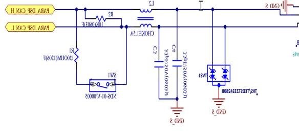
4) Is it recommended to add the resistance and capacitance between the CAN line? If so, what are the recommended parameters?

BR,

Gary
  • Hi Gary,

    1) Are the peripheral circuits and parameters of OSC required for R5? With a 25MHZ crystal oscillator, what is the capacitance value? (20MHZ crystal oscillator corresponds to 1MHZ CAN BUS);

    Please review the TCAN455x Clock Optimization and Design Guidelines application note for more information on determining the optimal values for the capacitors and the R5 resistor.  I think 470 ohms may be too large of a value based on my experience with other crystals I've looked at, but this will need to be verified.

    25Mhz is not a common frequency used in CAN, and may cause some timing related issues for CAN FD messages with Bit Rate Switching enabled for other nodes on the same CAN FD bus that use a different crystal frequency.  But 25MHz is a frequency within the working range of the TCAN4550.  However, the TCAN4550's datasheet timing parameters assume that either a 20MHz or 40MHz is used, and there is a bit in the configuration register to indicate which value is used.  If a 25MHz is used, then the 20MHz register selection should be used, but the timing values such as the watchdog and other timers, will need to be scaled according to the difference. 

    2) Do we have discrete RST circuit to share? Since we don't want to use the MCU.

    For reference schematics, I would suggest you review the User's Guides for the TCAN4550EVM or the BOOSTXL-CANFD-LIN.  The RST input is Active High, so it should be held Low for normal operation and then pulsed High to initiate a Reset Event.  Note that the RST pin is considered a Digital Input pin, so it should be references to the VIO supply voltage (3.3V) with an Absolute Maximum of 6V.

    3) SPI interface signals are directly entered into the control module. Do you have recommend guideline for those parameter requirements, such as current limiting resistors, filter capacitors, etc. ~

    We don't have any specific recommendations, but it is common to include a series resistor (usually 330 ohms or less) on the transmit side of the SPI signals to help dampen any signal reflections that may occur.  I don't usually see filter capacitors on SPI signals.  However, this is an application specific topic and other factors need to be considered such as the overall routing length and the parameters of the MCU.  The SPI voltage level and timing parameters are provided in the datasheet.

    4) Is it recommended to add the resistance and capacitance between the CAN line? If so, what are the recommended parameters?

    There are no specific requirements to add resistance and capacitance on the CANH and CANL, so I don't have a recommendation.  Adding these components adds to the overall bus loading, but I do see many customers add a small amount of capacitance to help filter high frequency noise.  I also see there is a 22pF cap between CANH and CANL, and this is something I can't recall seeing before.

    Additional comments from reviewing the schematic:

    • The nINT pin is an open-drain that requires a pull-up resistor to VIO.
    • The SPI Chip Select input should be High when idle, and it is common to see a pull-up resistor to VIO.
    • Please consider the ESD2CANFD24-Q1 for the CAN bus ESD protection

    Regards,

    Jonathabn

  • Hi Jonathabn,

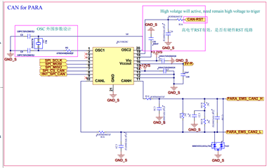
    Thanks for your support. We update the schematic. Please have your help to review, if you have any suggestion.

    BR,

    Gary

  • Hi Gary,

    The updates look OK to me.  I don't have any additional comments.

    Regards,

    Jonathan