Tool/software:
I want to use the IBIS model to use it in CST StudioSuite, an electromagnetic simulation software, but I don't know how to connect it. How should I connect the pins of the IBIS model and with what signals?
This thread has been locked.
If you have a related question, please click the "Ask a related question" button in the top right corner. The newly created question will be automatically linked to this question.
Tool/software:
I want to use the IBIS model to use it in CST StudioSuite, an electromagnetic simulation software, but I don't know how to connect it. How should I connect the pins of the IBIS model and with what signals?
Hi Unai,
I am unfamiliar with this software, we typically use ADS for IBIS simulation.
May I ask the stage of design with DP83848 you are on? Support for this part is limited as it is older, we recommend moving to DP83822/DP83826 if possible.
Thank you,
Evan
Hi,
CST Studio suite is an electromagnetic simulation software that in this case I want to use to obtain the radiated emissions of the ethernet communication of our PCB circuit. In this communication we use the DP83848J.
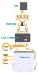
To simulate the circuit from the ethernet connector to the PHY (DP83848J), I must define the signals that go through the communication lines (TX, RX) and I wondered if you have a simulation model (IBIS...) and tell me how to make the connections with this model. The circuit I want to simulate is the following so that you have an idea:

If you need more information, tell me.
Regards,
Unai
Hi Unai,
I will check with the team and get back to you early next week.
Thank you,
Evan
Hi Unai,
Our PHY IBIS models do not support simulation on the MDI signals. Please let me know if you need support with simulation on the MAC-side signaling.
Thank you,
Evan
Knowing now that I can't use your IBIS model to simulate the MDI signals, would there be any other way to be able to represent the MDI circuit with RLC components and thus be able to simulate it in CST? In CST I can recreate the circuit with RLC components, but the problem is that I don't know how to represent the termination of each line or the input. Can you tell me the RLC circuit of the MDI?
Thank you,
Unai
Unfortunately we do not have this information available for MDI side connection, I cannot share RLC network to emulate the same line characteristic.
I recommend ordering an evaluation board for DP83848 so data can be gathered experimentally instead.
Thank you,
Evan