This thread has been locked.

If you have a related question, please click the "Ask a related question" button in the top right corner. The newly created question will be automatically linked to this question.

TPD3E001: How to prevent our 5V USB ESD diode to be damaged by bad USB chargers?

Part Number: TPD3E001
Other Parts Discussed in Thread: BQ25302, TVS2200, , TPD2E2U06

Tool/software:

Hello,

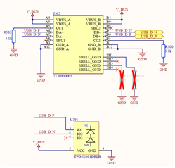
currently we are using TPD3E001DRLR as ESD diode for our 5V USB interface.

To VBUS we have connected the charger BQ25302RTER, which generates V_SYS (BQ25302, pins 13+14).

The fuel gauge BQ27427YZFR is connected between a Li-Ion battery and V_SYS.

Normally when an USB charger is connected to our device, the ICs will decide that only 5V may be applied to VBUS.

Unfortunately we cannot control which charger will be connected to our USB port.

Badly designed chargers may directly connect 24V to VBUS, which would not damage the charger (abs. max 28V, operating 6.2V), but would damage the ESD diode (max. 5.5V).

Is there component which could be added to the schematic to prevent the ESD diode to be damaged in such case?

Or maybe even completely different components which can cover such case?

Thank you very much in advance.

Kind regards

Daniel

  • Hi Daniel,

    It may be possible to use a Zener diode here for this application, as Zeners can be used for voltage regulation and from my understanding, that is the request here. TI is currently working on releasing a family of Zener devices, but these are not only still in development, but the voltages being released in the first phase are not lined up with the use case here. 

    If this is not a suitable solution, the Power Switches team may have an option here. I am not very familiar with their portfolio but I know we have worked with them on some USB solutions in the past.

    Best Regards,

    Josh Prushing

  • These chargers can easily output 2A at 24V. That would be a lot of heat for this one zener diode. Maybe I have to ask in the power switches team. Thank you.

  • Daniel,

    Apologies, looks like I was a little late in catching you before you posted on the other forum. In talking this over with a colleague, I believe I might've mis-understood the issue here. If the solution you are looking for is just an ESD device that can withstand the 24V short, TVS2200 would be a suitable device. 

    Again, apologies for the confusion, please let me know if you have any additional questions!

    Best Regards,

    Josh Prushing

  • Hello Josh,

    thank you for your response. Sorry, maybe I was not very clear in my initial post.

    Here is the relevant schematic with the current ESD diode.

    This is a USB 2.0 interface with an USB type C connector.

    The normal V_BUS is 5V.

    USB_D_P and USB_D_N are connected to a STM32 controller, with pins which tolerate max. 5.5V.

    That's why TPD3E001 is used to reduce the voltage to 5.5V in an ESD scenario.

    Now it is possible that a badly designed charger will be connected to our device and will output directly 24V to VBUS.

    If I now use your suggested TVS2200 the TPD3E001 will still be damaged when 24V are connected to VBUS.

    Maybe I did get something wrong?

    Thank you very much in advance.

    Kind regards

    Daniel

  • Hi Daniel,

    Thanks for the additional clarification here.

    So to ensure I am understanding correctly, the issue is that a 24V signal can come across the VCC of the TPD3E001, where this can only handle a maximum of 7V? If this is the case, would it be more beneficial to use only a 2 channel device to protect the D+ and D- lines of the USB connector, and if protection for VBUS was required, use a separate device for that use case? We have many 2 channel devices to choose from that do not have this VCC connection, and many higher voltage single channel options to protect the VCC connection. Would this be of interest? The two channel options will likely be much cheaper as well. Please see the image below for some options that would have similar or superior performance to TPD3E001 with only 2 channels:

    Please let me know if you have any questions!

    Best Regards,

    Josh Prushing

  • Thank you very much Josh. This seems like a reasonable solution!

  • Hi Josh,

    I'm coming back to this question. In theory it would also be possible to disconnect the VCC pin of the TPD3E001DRLR from V_BUS and basically have the same effect as with a TPD2E2U06. Is this correct?

    Thank you very much in advance.

  • Hi Daniel,

    If you leave the vcc pin of TPD3E001 floating the breakdown voltage of the input pins would increase to 10V, it would still clamp ESD strikes but at a higher clamping voltage.

    Regards,

    Sebastian