This thread has been locked.

If you have a related question, please click the "Ask a related question" button in the top right corner. The newly created question will be automatically linked to this question.

TCAN1145-Q1: TCAN1145 review schematic

Part Number: TCAN1145-Q1

Tool/software:

Hi, Support Team

our client use TCAN1145-Q1 as below chart, have any concern?

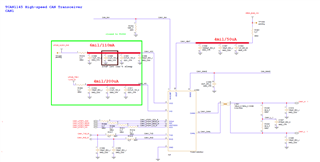
if any suggestion, Please advise me.

Thanks,

Best regards,

Lawrence

  • Jasper,

    An engineer has been notified of this post and will respond accordingly. Thanks for your patience.

    Regards,

    Eric Hackett 

  • Hi Lawrence,

    This schematic looks good. I don’t have any major changes to recommend. See my notes below.

    • Decoupling capacitors included and valued appropriately.
      • Current estimate for Vsup pin is undervalued. Max Isup current is 1.5mA in normal mode. Consider revising design if necessary for current needs of trace.
    • Split capacitor included and valued appropriately.
    • Bus capacitors included and valued appropriately - ensure placement close to connector and along signal path.
    • TVS diode not included - no issue. Perhaps on other schematic sheet near connector?.
    • Termination resistors included correctly and valued appropriately for end node.
    • CMC placed nominally between transceiver and termination.
      • Consider optional bypass 0-ohm resistors in case CMC is not needed.
    • All pull-up / series resistances are acceptable.

    Let me know if there are any questions or concerns regarding the design.

    Regards, 
    Eric Schott