This thread has been locked.

If you have a related question, please click the "Ask a related question" button in the top right corner. The newly created question will be automatically linked to this question.

TUSB320LAI: TUSB320LA

Part Number: TUSB320LAI
Other Parts Discussed in Thread: BQ25756, LM74930, TUSB320

Tool/software:

Hello,

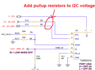
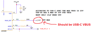
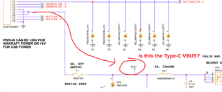
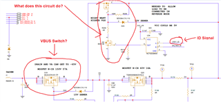
I am posting 2 pages from a schematic design that uses a TUSB320LA along with a BQ25756 and a LM74930.

I would greatly appreciate a detailed review on whatever portion is appropriate.

Thanks,

DanBRIDGE-SCHEMATIC-REV6-TI review-06-28-2024.pdf

  • Hi Dante,

    I remember you were working on a USB-C port with a unique connector awhile back. I have a few comments on this schematic that I'll list below:

    1. You need to have pullup resistors on the SDA and SCL lines connected to the TUSB320. I didn't see pullups on these nets in your schematic, so make sure these are present somewhere in the design.

    2. You have the VBUS_DET pin pulled up to an internal power rail. This should connect to the USB-C VBUS so our CC controller detects when VBUS is applied.

    Is VEXT the VBUS coming from the Type-C connector? If this is the case, then VBUS_DET should connect to VEXT

    3. I'm confused on how you're using the ID pin from the TUSB320 to control the Type-C VBUS. It seems that Q19 is your VBUS switch, but I can't tell how the ID signal is enabling/disabling this switch:

    Your VBUS switch should enable when ID goes low. This would mean your device is providing power on the Type-C VBUS. The VBUS switch should disable (disconnect) when ID is high.

    Best,

    Shane 

  • Shane, thank you for the review. I will respond in detail tomorrow.

    Dan

  • 1) These pullups were on another page

    2) Our situation is a little different than most. I have the following questions

    a) Do we need to detect VBUS when we are a device?

    b) Do we need to detect VBUS when we are a host?

    c) What is the timing required for VBUS detect, can I apply a VBUS to the VBUS_DET pin after the CC negotiation and ID has been asserted?

    3) This is a good question. Our board is a little complicated.

    a) We can operate in forward mode when means we receive power from an external source. In that case we are a device and the USB_ID is high.

    b) If we want to be a host we need to operate our power switch in a reverse mode. The circuit you pointed to allows that to happen with regard to the LM74930 device. So, if USB_ID is low and our onboard processor is ready this reverse mode is enables and we can provide power out of the board from VINT to VEXT. The normal forward mode is power being delivered to the board from VEXT to VINT. 

    I had to design this circuit because the LM74930 does not explicitly support a reverse mode. This was validated on the bench with an eval board and reviewed by TI.

    So I guess, going back to (1) maybe a need a switch version of VINT to be applied to VBUS_DETECT on the TUSB? The switched version would only be present when we are a host trying to drive power out.

    Maybe you can explain in detail what VBUS_DET does inside the TUSB part?

    If seems VBUS_DET is only important for UFP mode, i.e. when we are a device?

  • Please answer ASAP

  • Hi Dante,

    2a. Yes

    2b. If you are in DFP only mode, you do not need to connect VBUS_DET. For a DRP, you do need to connect this pin

    2c. The Type-C port should finish CC negotiation and assert ID before VBUS is applied. The order is: CC negotiation --> ID asserted --> VBUS applied

    3b. If you've validated that the circuit works then that is ok. The important thing is that your board does not provide VBUS until ID is pulled low on the TUSB320.

    Maybe you can explain in detail what VBUS_DET does inside the TUSB part?

    VBUS_DT is used to transition between multiple parts of the Type-C state machine inside the TUSB320. Here is an image of the state machine with areas where VBUS detection is needed.

    Best,

    Shane