


Other Parts Discussed in Thread: TSD05, ADS124S08
Tool/software:
Hi everyone:
I’m looking for parts / design recommendations to enhance the EMC of our device and to provide it with additional ESD / Surge protection. Currently there is no certification to be achieved, but we would like to implement everything we can to improve the robustness of our devices used in industrial settings where the surrounding electromechanicals are ageing and producing a growing variety of EMI.
Our device measures temperature using a RTD PT100 with 3 wires aiming an accuracy of +-0.1oC. We have our first hardware prototype tested and working pretty well.
However, the RTDs are attached to the device using cables ragging from 3 to about 15 meters. Those cables are the “Coupling Paths” for the “Noise Sources” that affect the Systems like ours according to EMI literature.
In respect to improve the EMC of our devices, we went with the route of implementing TVSs as proposed on this article from ADI which uses the same part we are using as the RTDs frontend, an LTC2986. However, implementing those TVSs the accuracy was affected as the impedance readings increased around 0.8 ohms compared to the devices with no TVSs installed. The conclusion is that the reverse leaking current of 800uA of the SMAJ5.0A is not acceptable.
We came across the TVS0500 whose 70pA Leakage Current at our ambience temp seems to be a huge improvement over the previous part. However, all this theory and devices are pretty new to us and this is where we would like to ask for your help to confirm if the following is correct or not:
1.
Is the Working/Breaking Voltage of the TVS0500 correct to protect the LTC2986?
Considering this from the datasheets:
| Part | Working Voltage | Clamping Voltage (max) |
|
TVS0500 |
5V |
9.2V at 43 A (8/20us) |
|
SMAJ5.0A |
5V |
9.2V at 43.5A |
Now, considering the IC to be protected, its actual operating voltage is 3.3V and its absolute max on its channels pins is 3.0V 3.6V (I took the liberty to assume that, as the datasheet says it is VDD-0.3 which seems to me like a typo).
Anyway, to determine the max voltage that the protection device should provide, I have learnt from other responses in this forum that the max indicated in the datasheets apply for the continuous DC voltage and it is generally accepted to assume the “peak” max will be higher. The proper way to do determine it is plotting the PLT curve for the device to be protected, but sadly we don’t have the resources to do that. However, we can take as a reference, that so far, none of the 12 channels that we have deployed on the field have failed, all of them with SMAJ5.0A installed and running continuously on the machine with the worst EMI conditions. So we may also assume that the protected ICs are capable of handling 9.2V peaks.
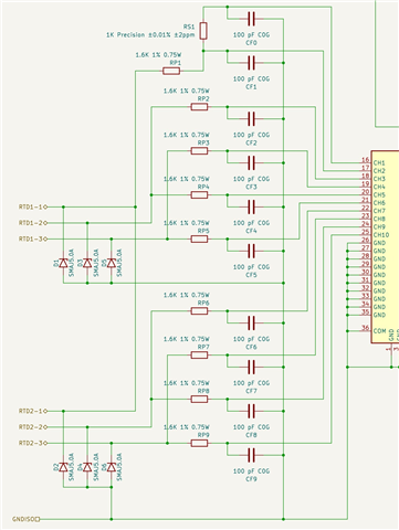
I should explain that while it is normally not expected 24V continuously at the RTDs inputs, we wanted to consider the cases of misconnections and shorts of the system’s power source with the RTDs wiring. We implemented then series resistors between the TVSs and the protected IC. We calculated that those 1.6Kohm resistors at 24VDC will provide at most 15mA which is permitted by the IC on its channels according to its datasheet. It may also be worth to note that the resistors are not affecting negatively the accuracy sensor, which as we have learnt, is a usual compromise in these cases.
All this to say that the voltage permitted in our actual implementation of the IC is not 3.3V but instead 24V, right? Here it is the relevant part of the schematic:
2.
Following the above, if we agree that the max continuous voltage of our circuit is 24V, will it be a mistake to choose the TVS0500 as it will be damaged if subjected for that voltage for a while?
3.
Following the above, if the TVS0500 is not suitable, the next best option is select a TVS (Or Flat-Clamp IC) that specifically operates at 24V and recalculate the actual protection resistors to make sure their values go over the clamping voltage of the selected protection device. Am I right?
In that way, the RTDs inputs are protected for continuous 24VDC and also form voltage spikes over it. However we should re-check that the accuracy of the system won’t be affected.
4.
Finally, a generic check about what are we really accomplishing: As far I understand, the Flat-Clamp ICs / TVSs offer various levels of ESD and Surge protection. Still, the undesired voltages produced by the EMI on the field are going to be present, but capped to a level that won’t hurt the deice, but anyway, it will be still be accounted by the circuit to produce its results. So far we have dealt with this issue oversampling and implementing software filters. We are satisfied with the results, but I wonder if there is something else on the hardware side - hopefully ready made - for this kind of situations.
Any tips, would be greatly appreciated.
Thank you all!


