This thread has been locked.

If you have a related question, please click the "Ask a related question" button in the top right corner. The newly created question will be automatically linked to this question.

DS90UB954-Q1: Needed Layout Suggestion for DS90UB954-Q1

Part Number: DS90UB954-Q1

Tool/software:

Hi TI,

     We have some doubts about the Layout and would like to verify them with you and they are as follows:

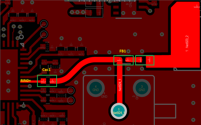
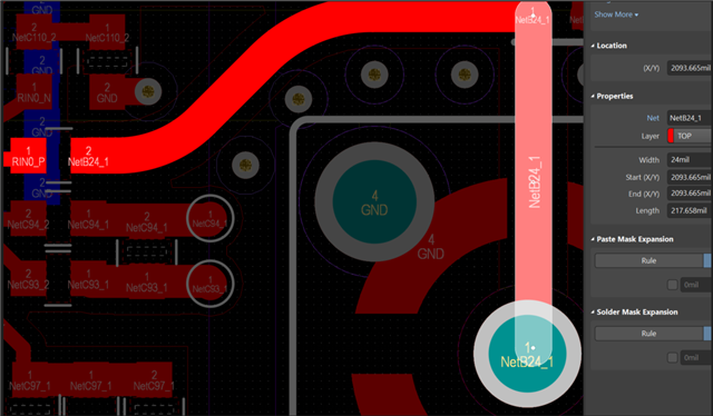
  •   Can the trace width between Cac1 and the Coaxial connection be kept at 24 mil?
     
  •   Also, could you confirm the placement and routing flow between Cac1 and FB1 can be kept like this?
  • Hi,

    Please see feedback below:

    1. Trace impedance should be kept at 50 ohm throughout the FPD-Link channel. Please update trace width accordingly based on stack-up of your PCB.
    2. The AC coupling capacitor for the RIN0+ pin should be placed near the des, with the ferrite bead / inductor which is used for PoC being placed on the HS trace.

    Best,

    Thomas