Part Number: HD3SS3212
Other Parts Discussed in Thread: TUSB542
Tool/software:
Hello support team,
I want to use USB7206C (microchip) where UFP port will be USB-C with HD3SS3212 MUX.
I would like to confirm some information's..
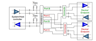
1. Will be HD3SS3212 suitable for my application? - 10gbps usb hub, length of usbC cable max 0.5, length of pcb traces about 50mm for UFP port. Or it is necessary to use mux with redriver?
2. According to datasheet typical application - B0 and B1 are connected to the first row of usbC. C0 and C1 is connected to second row of usbC. First row of usbC is assigned to CC1 and second row is assigned to CC2 right? And cable orientation detection also depends on CCx, right?
I need to swap B0, B1 with C0, C1 because of my PCB layout. So, I connect 1row of usbC to C0, C1 and 2row to B0, B1. I can do this, right? Than when I swap it, cable orientation signal for mux will need to be inverted too, right? Because of correct Superspeed pair connected.
3. I am confused if I need to use AC coupling capacitors on both side of MUX HD3SS3212 in my application or not. Could you help me with this? In my first design with USB5744 and TUSB542 I use AC coupling capacitors on both sides.
Thank you
Best regards,
Martin